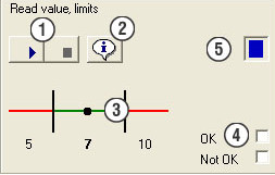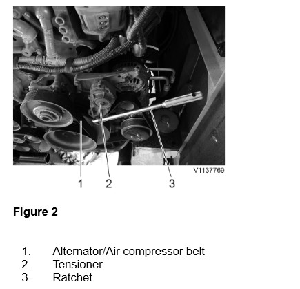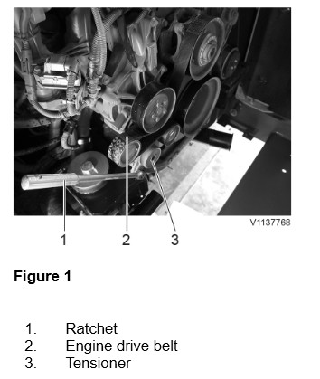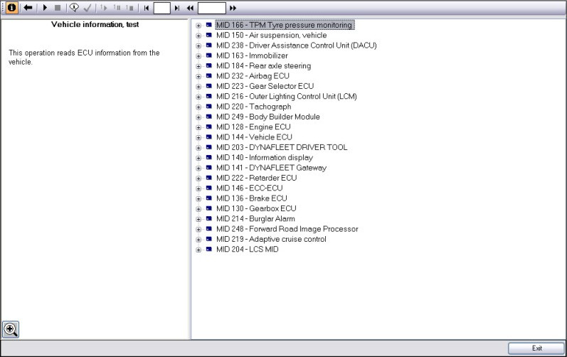
This instruction show you guide on how to use Volvo techtool diagnostic software and VOCOM 88890300 do perform test and calibration for Volvo version 2 and old truck.This section describes the functions available in the window when an operation has been opened. The illustration shows a typical test/calibration operation. When programming, a list of programming parameters is shown in field 5.
What your need?
2025 Volvo Techtool PTT 2.8.310+ACPI 0.7.1.0 High Level+Devtool

Toolbar
The following function buttons are available in the toolbar.
Information text – click the button to display/hide the text and image field.
Close – click the button to stop an operation and return to the previous view. Alternatively, use the Esc key. 
Open – click the button to open an operation.
Start – click on the button to start the current operation, or use Ctrl + Space Bar.
Stop – click on the button to stop the current operation, or use Ctrl + Space Bar or Esc.
Default information – click the button to display the same information in the text and image field as when the operation was started.
Prerequisites – click the button to display the conditions for the implementation of the operation and the status of conditions.
Start replay – click the button to start playback of the selected operation.
Pause replay – click the button to pause the playback of the operation. Restart the playback by clicking Start replay.
Stop replay – click the button to stop playback of the operation.
Rewind – click on the button to quickly rewind an operation manually.
Previous session – click on the button to jump to the previous session manually.
Next session – click on the button to jump to the next session manually.
Forward – click on the button to fast-forward an operation manually.
Session number – states which session is being played.
Session time – states how far into a session you are.
Wiring schematics
The wiring schematics shown by clicking on a link in the text field are to be used as a functional description. The schematic shows the conditions that apply when the function is active.
Note: The wiring schematics are not to be used as a basis for circuit measurements.
Cable colors
There are four colors – red, blue, green, and black – used on the wiring schematics
Red is only used for power supply, irrespective of whether it is battery voltage or a supply from a control unit (for example, 5 V).
Blue is used for wires connected to a grounding point even if they are indirectly connected, i.e. via a control unit.
Green is used for signal cables, primarily to indicate the signal cable from a sensor.
Black is used where the function of the cable is not relevant or where the cable cannot be categorized according to the other colors.
Checking conditions
Click this button to check the condition’s status. You can check conditions at any time except when the actual operation is being run. If the button is grayed out, there are no conditions for the operation.
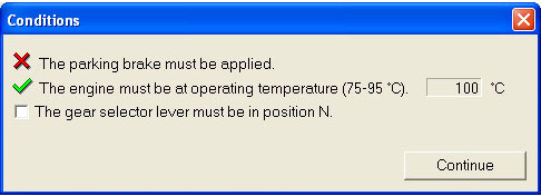
Once an operation has been started, the conditions for implementing the operation are checked. In certain cases conditions are checked even after an operation has been exited.
A window containing conditions and their statuses is displayed. The following status markings are available.
Green marking – Condition fulfilled.
Red marking – Condition not fulfilled.
Grey marking – Condition not yet checked
Check box – Condition that must be checked manually: for example, blocked wheel. When a manual check has been carried out the check box must be checked.
In certain conditions, the sensor value on which the status marking is based is displayed.
Click Cancel to cancel the check.
Presentation element
This section gives a general description of the available presentation elements.
Most presentation elements contain the following components.
