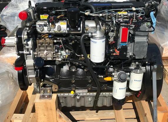
Here is the instruction show you guide on how to remove and install water pump for Perkins 400A and 400D engine.
Related Contents:
Perkins Communication Adapter 3 27610402
Perkins SPI2 2018A Service and Parts Catalogs
Removal Procedure
Start By:
a Remove the fan. Refer to Disassembly and Assembly, “Fan – Remove and Install” for the
correct procedure.
b If necessary, remove the alternator. Refer to Disassembly and Assembly, “Alternator –
Remove and Install” for the correct procedure.
1 Drain the coolant from the cooling system into a suitable container for storage or disposal. Refer to Operation and Maintenance Manual, “Cooling System Coolant – Drain” for more information.

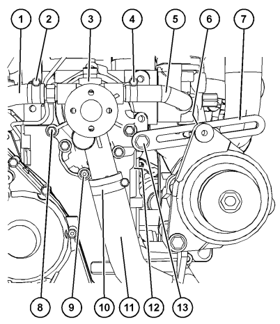
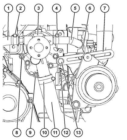
2 Loosen hose clamp (10) and disconnect hose (11) from water pump (3).
3 Loosen hose clamp (2) and disconnect hose (1) from water pump (3).
4 Loosen hose clamps (4) and disconnect hose (5) from water pump (3) and the thermostat housing
5. Remove bolt (13) for alternator bracket (7).
Position the alternator bracket away from water pump (3).
Note: The alternator bracket on some engines is
secured by two bolts.
6 Remove bolts (8) and nut (9) from water pump (1).
Remove the water pump from the cylinder block.
Note: If necessary, gently tap the water pump with a soft faced hammer to loosen the water pump.
7 Remove gasket (12) (not shown).
Installation Procedure
1 Ensure that the gasket surfaces of the water pump and the cylinder block are clean and free from damage.
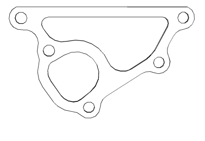
Correct orientation of the water pump to block gasket
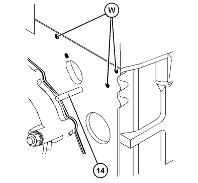
2 Ensure that the bolt holes in Position (W) and stud (14) are clean and free from oil and coolant.
3. Install a new gasket (12) (not shown) over stud (14). Ensure that the gasket is correctly oriented.

Water pump bolts and nut tightening sequence
4 Apply Tooling (A) to the first two threads of bolts (8) and nut (9).
5 Install water pump (3).
6 Install bolts (8) and nut (9) hand tight. Ensure that gasket (12) (not shown) is correctly positioned.
7 Tighten bolts (8) and nut (9) to a torque of 5 N·m (44 lb in)
8 Tighten bolts (8) and nut (9) to a torque of 10 N·m (89 lb in)
9 Connect hose (1) to water pump (3). Securely tighten hose clamp (2).
10 Connect hose (5) to water pump (3). Securely tighten hose clamp (4).
11 Connect hose (11) to water pump (3). Securely tighten hose clamp (10).
12 Position alternator bracket (7) onto water pump (3). Loosely install bolt (13) to the alternator
bracket.
Note: The alternator bracket on some engines is secured by two bolts.
13 Fill the cooling system with coolant.
