Posted on

How to Solve Perkins 1106D EPG CID 1785 FMI 10 Trouble?

Perkins 1106D electric power generation trouble code CID 1785 FMI repair solution.
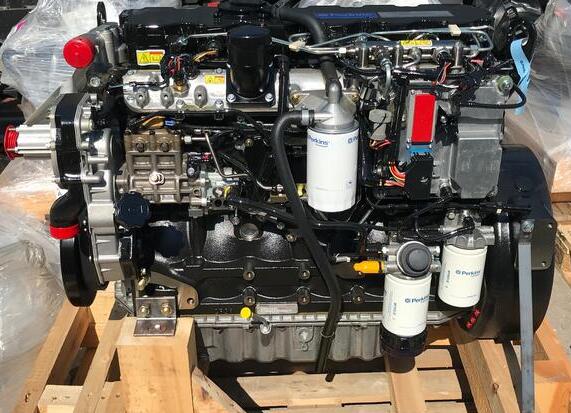
Perkins 1106D EPG Engine CID 0172 FMI 04 Trouble Code Solution
Related Contents:

Perkins Communication Adapter 3 27610402

Perkins EST 2024A

Perkins SPI2 2018A Service and Parts Catalogs


Conditions Which Generate This Code:
This diagnostic code is designed to detect the loss of the 5 Volt supply at the sensor connector.
The Electronic Control Module (ECM) detects the following conditions:
• The engine speed is more than 1000 rpm.
• The intake manifold pressure is within the acceptable range.
• No 0262 codes for the 5 Volt supply are active.
• Diagnostic code 0168-01 is not active.

System Response:
If equipped, the diagnostic lamp will flash and the derate lamp will come on. The diagnostic code will be logged.


The ECM will flag the intake manifold pressure as being invalid. A default value is used for the intake
manifold pressure.
Note: Any open circuits or short circuits in the signal wire for the oil pressure may reset this diagnostic.

Possible Performance Effect:
For engines with an electronically controlled wastegate, the current for the wastegate solenoid
will be set to a default value while this code is active.

This will cause the engine to have poor acceleration but the default setting will prevent any overpressure in the intake manifold which could be caused by an overspeed of the turbocharger.
The engine will be derated.

Troubleshooting:
This diagnostic code will detect the loss of the 5 Volt supply to the sensor.
Perform the following diagnostic procedure: “Engine Pressure Sensor Open or Short Circuit – Test”

Results:
• OK – STOP.
Posted on

Perkins 1106D Engine Power CID 0342 FMI 08 Trouble Repair

Perkins 1106D EPG Engine CID 0172 FMI 04 Trouble Code Solution

There is the instruction show you guide on how to solve Perkins 1106D engine power generation CID 0342 FMI 08.

Perkins 1106D EPG Engine CID 0172 FMI 04 Trouble Code Solution

Related Contents:

Perkins Communication Adapter 3 27610402

Perkins EST 2024A

Perkins SPI2 2018A Service and Parts Catalogs


Conditions Which Generate This Code:
The Electronic Control Module (ECM) detects the following conditions:
• The signal from the secondary speed/timing sensor is lost and/or intermittent.
• The signal from the secondary speed/timing sensor was lost for at least 2 seconds while the signal

from the primary speed/timing sensor remained valid and the engine was running.
• Diagnostic code 0168-01 is not active.
• The engine has been running for more than 3 seconds.
• No 0041 diagnostic codes are active.

System Response:
If equipped, the diagnostic lamp will flash and the diagnostic code will be logged.

Possible Performance Effect:
If the signal from the secondary speed/timing sensor is lost and the engine is stopped, the engine will not restart. The performance will not be affected unless both speed signals are lost. The loss of the signals from both speed/timing sensors will cause the ECM to shut down the engine.

Troubleshooting:
This diagnostic code indicates that the signal from the secondary speed/timing sensor is incorrect.

Perform the following diagnostic procedure: “Engine Speed/Timing Sensor Circuit – Test”

Results:
• OK – STOP

Posted on

Perkins 800 Series Industrial Engine Fuel Injector Test

Perform the following procedures in order to determine if a fuel injector does not work correctly.
Bench test the fuel injectors at a temperature of 18° to 20 °C (64° to 70 °F).

What you Need?

Perkins EST 2023A Diagnostic Software

Perkins Communication Adapter 3


Procedures:

1 Run the engine at low idle.
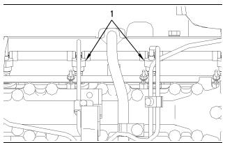
2 Loosen the connection for the high pressure fuel line (1) at the fuel injector on No. 1 cylinder. Do not loosen the nut more than half of a turn. Listen for the low idle to decrease or become rough. Tighten the nut for the fuel supply line on No. 1 cylinder.

Perform this test on each cylinder.
3The fuel injector is faulty when the nut for the fuel supply line is loosened and the following events occur:
• The engine rpm does not decrease.
• The engine does not idle roughly.


4 Remove the fuel injector for additional testing.
Note: If leakage occurs at the nut for the fuel supply line, make sure that the fuel supply line and the nut are correctly aligned with the inlet connection of fuel injector. Do not tighten the nut for the fuel supply line on the high pressure fuel line more than the recommended torque. If the nut is tightened more, the fuel line may become restricted or the threads of the fuel injector and the nut may be damaged.

Cleaning of the fuel injectors
Before a fuel injector is tested, remove any loose carbon from the tip of the fuel injector. Do not use abrasive material or a wire brush in order to clean the nozzle.
The fuel injector is not a serviceable part.

Disassembling or adjusting the nozzle will violate the standards for emissions.
Note: Extra care should be used in handling the fuel injector in order to prevent damage to the nozzle tip.
A scratch or a burr could cause needle leakage or spray distortion. Dirt in the orifices of the nozzle tip can damage engine components. Dirt can also distort the spray pattern of the nozzle.