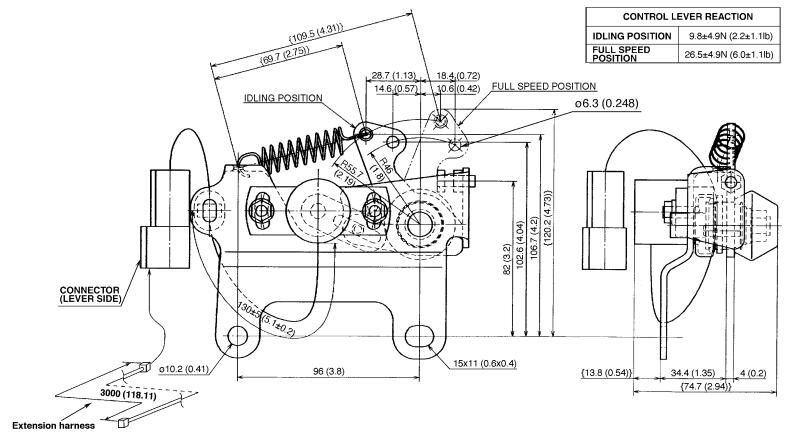
Outline figure of Engine Accelerator

How to install
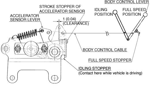
• Ensure that the body control lever is equipped with a full speed stopper, in order to control the stroke of the sensor lever.
• Adjust the body control lever so that the full speed stopper makes contact earlier than the stroke stopper of accelerator sensor.
• Ensure that the accelerator sensor lever will be in contact with the idling stopper by adjusting the speed control lever when the P.T.O. or equipment is not operating (during normal driving).
HINO Truck Service Manual 2022 Workshop Repair Book

[NOTE]
The clearance specified for the accelerator sensor stroke stopper is for reference only.
If the sensor side stopper comes into contact earlier, stresses will be imposed upon the sensor shaft and may result in damage to the parts.
Also, if the sensor lever does not come into contact with the idling stopper, it may result in improper engine operation during normal driving conditions.
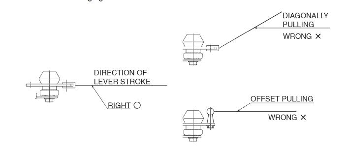
When installing the cable on the accelerator sensor lever, ensure that the cable pulls in a parallel direction to the lever stroke so that an imbalanced load is not applied to the sensor shaft. See the following figure.

Cautions when installing the engine accelerator sensor
• Do not attempt to disassemble the sensor.
• Do not drop or otherwise shock the sensor, as this will lead to malfunction.
• Prevent water intrusion or direct splash.
• The sensor operating range is -30°C to 80°C (-22°F to 176°F) and should only be used in that range.
• Avoid mounting the sensor in an area that may receive casual impacts.
• The sensor must be located in an area free of oil, dust, humidity, chemicals and vibration.
• If a well protected location is not available, then a cover must be installed.
• Install the wiring harness so that it is secure and not able to twist or bend.
• Refer to the Chapter 7 for instructions regarding installation of the harness.
• If the sub-harness is not long enough, extending the harness must be completed using the same type of wire.

