Posted on

How to Change Road Speed for Fendt Vario 700 COM III Tractor

Fendt tractors is popular on wordwide markets.And normally the Fendt tractors road speed limited about 30-40km,so many farmer owner want to change their Fendt tractors road speed to improve tractors work efficiency.Here autoepccatalog.com show you guide on how to use Fendt Fendias diagnostic software to change road speed for Fendt Vario 700 COM III tractor.


What your need?

AGCO 2×4 CANUSB Diagnostic Tool

Fendt Fendias Diagnostic Software

Some other cables (for some models,it requires you extra cable for programming function)


Note:Some tractor speed limited by ZF transmission,in this case it can not do direly by EOL,you need do extra steps to unlock it.


Procedures:

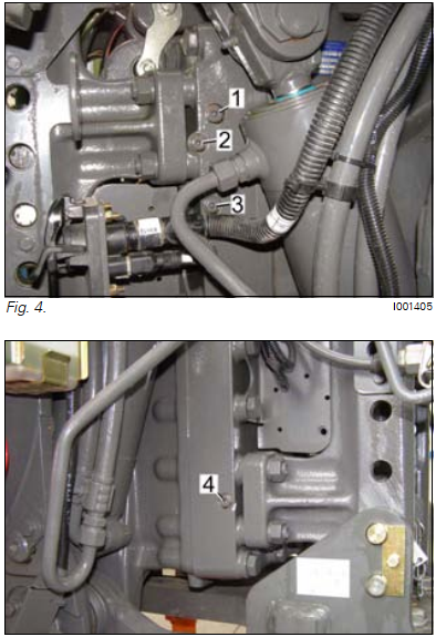
Connect AGCO 2×4 to Fendt tractor on G and K bus port.

Notice:here for this model,only need G and K bus connected.Different Fendt tractor need different connection wire cables.

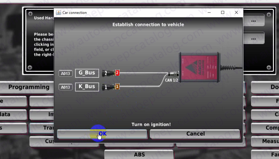
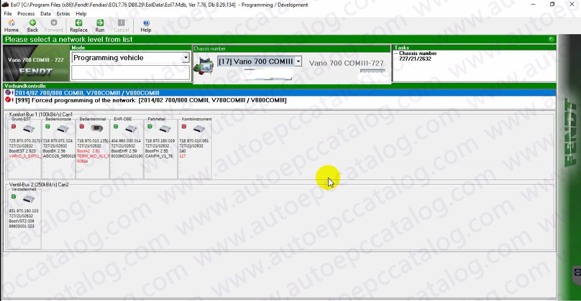
Run EOL 7.76,and select “Programming Development”then input your tractor chassis to build connection.

Road Speed for Fendt Vario 700 COM III Tractor (2)

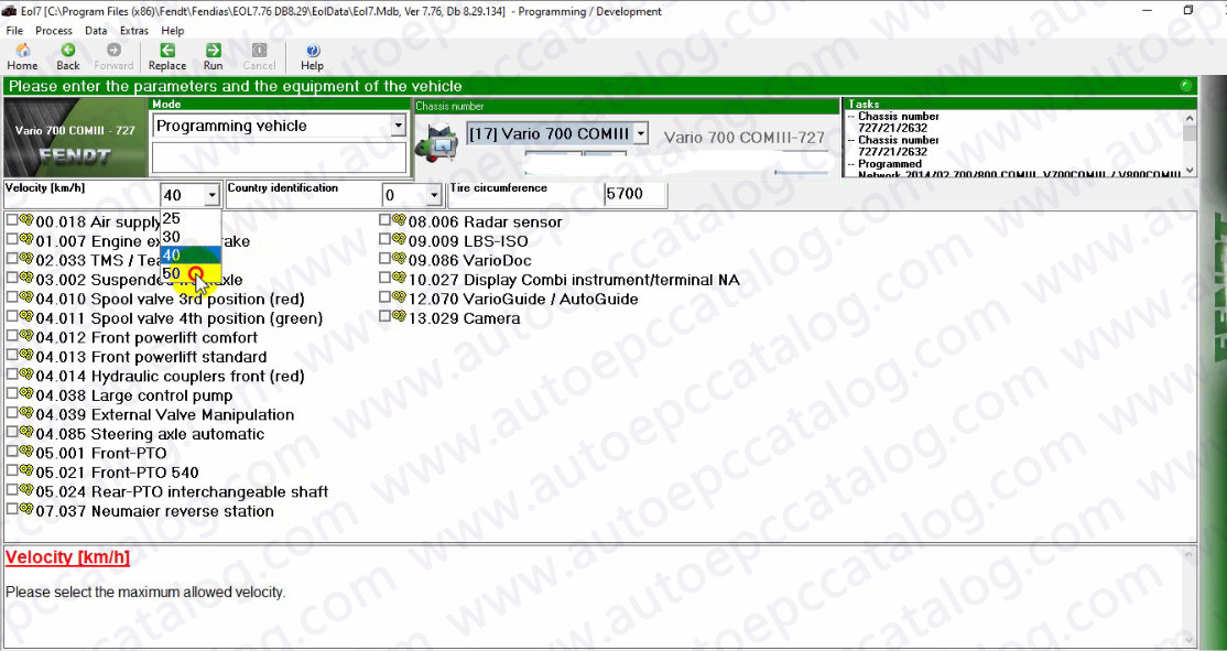
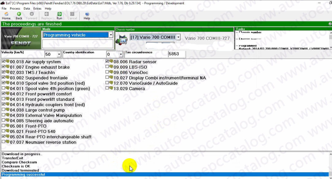
After then select the road speed parameters you want in the velocity field,and select equipment of the vehicle

Road Speed for Fendt Vario 700 COM III Tractor (3)

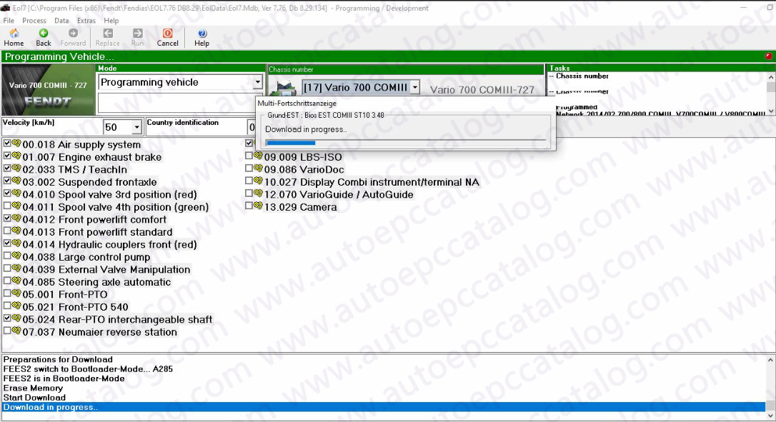
Then wait for EOL Programming for Fendt tractor,whole processing will take about 15-20 minutes

Just wait it finished

Road Speed for Fendt Vario 700 COM III Tractor (4)

Devices have been switched into the bootloader-Mode for programming!

Please carry out a Reset of the devices:

Ignition “OFF”

Wait 15 seconds

Ignition “ON”

Road Speed for Fendt Vario 700 COM III Tractor (5)

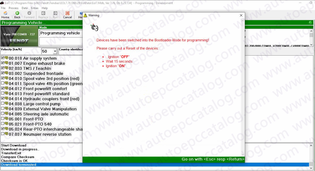
Now programming successfully!

Road Speed for Fendt Vario 700 COM III Tractor (6)

ATTENTION:Above steps are basic steps,it may require some other extra steps,try it at your own risk please.

Posted on

When Fendt 900 Varios Sensors Concerned Must Be Calibrated?

Fendt 900 Varios COM III

Fendt 900 Varios Sensors Concerned compensate for mechanical and electrical tolerances in sensors, the sensors concerned must be calibrated.If a sensor is replaced, it must be calibrated.

Fendt 900 Varios COM III

What Required:

FENDT Fendias v2.2024

AGCO 2×4 CANUSB


The following sensors and functions require calibration

1 Rear EPC calibration (depth control code 8001 and rear power lift position code 8002)

2 Calibration, EPC front (code 9001 and code 9002)

3 Calibration, crossgate lever (hydr. auxiliary valves) (code 1001)

4 Calibration, linear module 1 (hydr. auxiliary control vakve) (code 1003)

5 Calibration, linear module 2 (hydr. auxiliary control vawve) (code 1004)

6 Calibration, linear module 3 (hydr. auxiliary control valve) (code 1005)

7 Calibration, linear module 4 (hydr.auxiliary control valve) (code 1006)

8 Calibration, front axle suspension (code 7666)

9 Steering calibration (steering angle sensor code 2401/Autoguide control valve code 2403)

10 Calibration,rear PTO coupling time (code 6034)

11 Calibration,front PTO coupling time (code 7034)

12 Calibration,drive clutch pedal (code 4001)

13 Calibration,hand throttle pedal (code 2)

14 Calibration, travel range selector (code 4003)

15 Calibration, foot throttle pedal (code 4005)

16 Calibration, transmission ratio characteristic (code 4007)

17 Calibration, turbo-clutch function (code 4009)

18 Calibration, throttle pedal resolution (code 4010)

19 Calibration, heater valve (no code)


NOTE: Observe the calibration sequence.

Calibrations 1 to 11 and 19 can be performed in any order.

Calibrations 12 to 18 must be performed in sequence and en block (transmission calibration).The transmission emergency operation must not be switched on during calibration.(Transmission oil temperature higher than approx.409C during transmission calibration).If incorrect values are detected or the conditions are not met, an ERROR message appears If calibration completes successfully, OK is displayed, and the new sensor settings are stored.Data are only accepted when ignition key is turned to position “0”.(Wait for at least 15 seconds before switching on the ignition again!)

Menu levels on the A007 instrument panel

Posted on

FENDT 900 Vario COM III Transmission and Control Hydraulics Pressure Measuring Points

FENDT 900 Vario COM III Transmission and Control Hydraulics Pressure Measuring (7)

Here is the illustration show you pressure measuring points on FENDT 900 Vario COM III transmission and control hydraulics.


FENDT 900 Vario COM III Transmission and Control Hydraulics Pressure Measuring (1) FENDT 900 Vario COM III Transmission and Control Hydraulics Pressure Measuring (2) FENDT 900 Vario COM III Transmission and Control Hydraulics Pressure Measuring (3)


M14 Pressure,4WD clutch

M15 Pressure,differential lock

M16 Switching pressure,PTO 1000


Related Contents:

FENDT Fendias v2.2024

AGCO 2×4 CANUSB


The measuring connections at the rear right and left of the cover plate on the rear axle housing may also be used for checking the rear PTO.

NOTE: Measuring connection M16 is present from chassis number 9XX/2X/3501.


1 PTO clutch (Measuring connection M12x1.5)

2 Lubrication pressure,rear axle  (Measuring connection M10 x 1)

3 PTO control 540/750 (Measuring connection M10x1)

4 PTO control 1000  (Measuring connection M10 x1)

FENDT 900 Vario COM III Transmission and Control Hydraulics Pressure Measuring (4) FENDT 900 Vario COM III Transmission and Control Hydraulics Pressure Measuring (5) FENDT 900 Vario COM III Transmission and Control Hydraulics Pressure Measuring (6)


M1 System pressure

M2 Clutch pressure

FENDT 900 Vario COM III Transmission and Control Hydraulics Pressure Measuring (7)

Posted on

How to Solve Fendt MT1149 Tractor DEF Suction Line heater Short circuit Error

Fendt MT1149 Tractor

Here is the instruction show you guide on how to solve Fendt MT1149 tractor circuit on the DEF suction line heater control circuit.

Fendt MT1149 Tractor

Preparations:

AGCO EDT 2024

AGCO 2×4 CANUSB


Code SA 00 SPN 4340 FMI 03

Short circuit on the DEF suction line heater control circuit.


Diagnosis and solution

Clear the error log.

Restart the engine module.

If the fault code shows again during the next driving cycle, check the following.

Check the DEF suction line heater relay harness. Make sure the connections are good and the contacts are clean.

Replace the DEF suction line heater relay. If the system is correct and the fault code is not active, the original DEF suction line heater relay is bad.


Code SA 00 SPN 4340 FMI 04

Short circuit on the DEF suction line heater control circuit.


Diagnosis and solution

Clear the error log.

Restart the engine module.

If the fault code shows again during the next driving cycle, check the following.

Check the DEF suction line heater relay harness. Make sure the connections are good and the contacts are clean.

Replace the DEF suction line heater relay. If the system is correct and the fault code is not active, the original DEF suction line heater relay is bad.