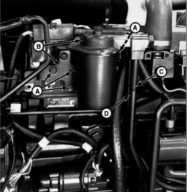
Here are step by step guide on how to install engine for JOHN Deere 5510 tractor without Cab.Same steps for 5210/5310 and 5410 tractors.
Related Contents:
John Deere Service Advisor EDL2
2024 John Deere Service Advisor 5.3.235
John Deere Parts ADVISOR EPC 2024
Steps:
1.Install clutch.
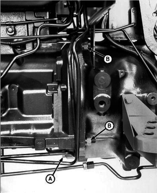
A – Cap Screw
B – Nut and Washer
NOTE:
Turning PTO shaft at rear of tractor during engine installation will aid in alignment of PTO clutch and shaft.
2.Put transmission shift levers in neutral to ease clutch shaft alignment with engine.
3.Apply multipurpose grease to end of PTO clutch shaft.
4.Install engine to clutch housing.
5.Install engine-to-clutch housing cap screws (A) and nuts and washers (B). Tighten to specifications below.

6.Align studs in engine with front end. Install front end to tractor. Tighten front end support-to-engine cap screws (A and B) and nuts (C) to specifications.
NOTE:
Hollow dowels are installed in bores of cap screws (B).
LV2295-UN: Tighten Cap Screws and Nuts
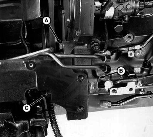
A – Cap Screw
B – Cap Screw
C – Nut
7.Pull wiring harness (C) and cable (B) through grommets.
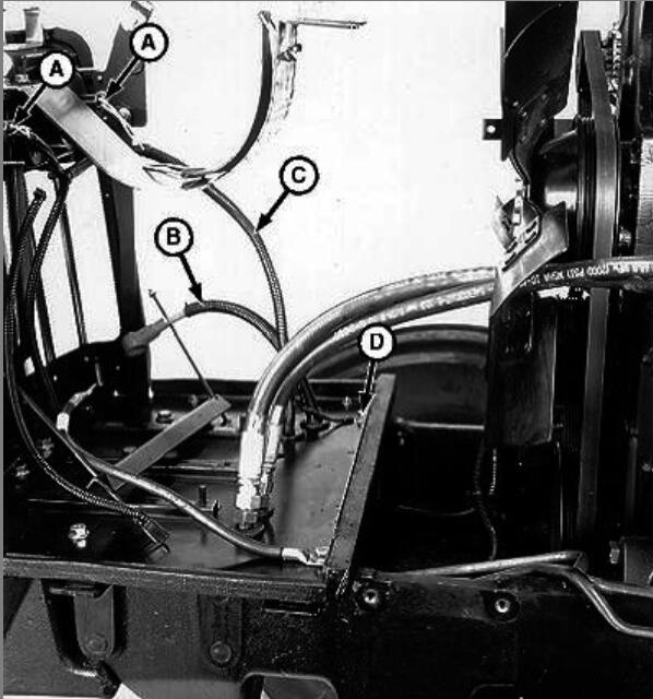
A – Headlight Wiring Connector
B – Positive (+) Battery Cable
C – Wiring Harness
D – Ground Cable
8.Connect wiring connectors (A).
9.Connect ground cable (D).
10.Remove wood blocks, floor jack, support stands, and lifting brackets.
11.Install muffler and exhaust pipe.
12.Connect wiring connectors (A and B).
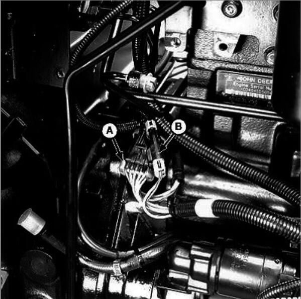
A – Wiring Connector
B – Wiring Connector
C – Fuel Return Hose
D – Right-Side Post
LV2290-UN: Wiring Connectors
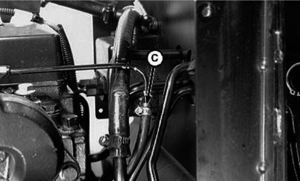
A – Wiring Connector
B – Wiring Connector
C – Fuel Return Hose
D – Right-Side Post
LV2291-UN: Fuel Return Hose
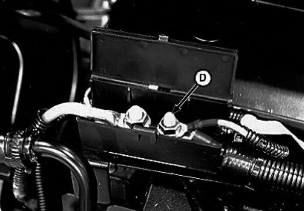
A – Wiring Connector
B – Wiring Connector
C – Fuel Return Hose
D – Right-Side Post
LV2293-UN: Right-Side Post
13.Connect fuel return hose (C).
14.Connect red wire lead #002C on right-side post (D) of fuse link junction block.
15.Connect hydraulic steering lines (A and B).
LV2292-UN: Hydraulic Steering Line and Oil Cooler Line
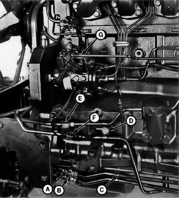
A – Hydraulic Steering Line
B – Hydraulic Steering Line
C – Clamp
D – Clamp
E – Oil Cooler Line
F – Oil Cooler Line
G – Throttle Control Rod
16Connect oil cooler lines (E and F).
17Install clamps (C and D).
18Install throttle control rod (G).
19.Install oil tubes (C and D) into engine oil cooler manifold.

LV2332-UN: Oil Filter and Bracket
A – Cap Screw (4 used)
B – Oil Filter and Bracket
C – Oil Tube
D – Oil Tube
20.Install oil filter and bracket (B).
21.Install four cap screws (A).
22.Install lines (A and B).
LV2289-UN: Suction Line
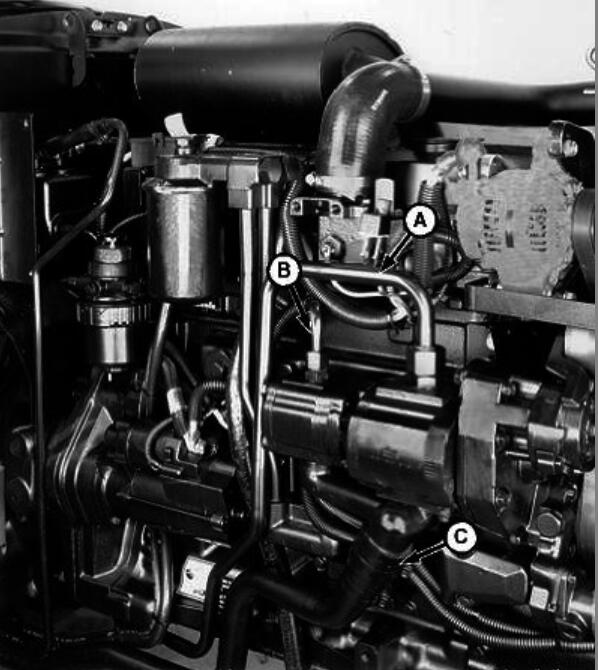
A – Line
B – Line
C – Suction Line
23.Connect suction line (C).
24.Install hydraulic line support clamp under right-side floor plate.
25.Install MFWD drive shaft, if equipped.
26.Install fuel filter/primer pump.
27.Install battery.
28.Install radiator.
29.Adjust fast idle.
30.Install hood.
