Here is the instruction show you guide on how to remove and install controller for Jungheinrich Junior AME13 forklift truck.
Jungheinrich JETI Judit-4 v4.37.001
Jungheinrich JETI SH 4.36 Forklift Service Information 2023
Jungheinrich JETI ET 4.37 EPC Updated 492 Spare Parts Catalog
Disassembling the controller
Requirements
Truck parked securely – see operating instructions.
Procedure
Disconnect the battery connector and lift out the battery – see operating instructions.
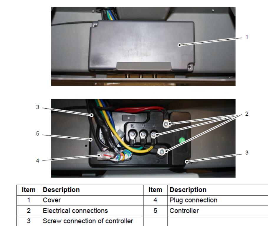
The controller is underneath the battery.
Remove the cover (1) of the controller (5).
Detach the electrical connections U, V, W, B+ and B- (2).
Undo the plug connection (4).
Undo the screw connections on the controller housing (3)
Lift out the controller (5).
Controller removed.
Fitting the controller
Requirements
Truck parked securely – see operating instructions
Procedure
Insert the controller (5).
Fit the controller (5) in place.
Re-establish the plug connection (4).
Connect the electrical connections U, V, W, B+ and B- (2)
Fit the cover (1) of the controller (5).
Insert the battery and connect the battery connector Controller fitted.
A teach-in of the controller is required after replacement. Otherwise, an error is indicated by means of a flashing code (4x long and 3x short).
Controller teach-in
Jack up the truck – see operating instructions.
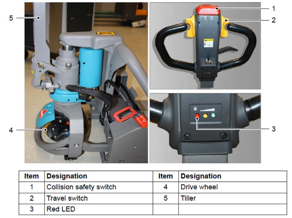
Move the tiller (5) to home position.
Press and hold both the collision safety switch (1) and travel switch (2) for a short time.
The teach-in process starts and takes approx 2 to 2.5 minutes. During this process, the drive wheel (4) rotates in different directions and at different speeds
The teach-in process is finished when the red indicator lamp (3) stops flashing.
Do not interrupt the teach-in process.
Start up the truck and carry out a function check – see operating instructions.