Posted on

HITACHI ZX-6 Coolant Control Valve Operation Check Machine

HITACHI ZX-6 Coolant Control Valve Operation Check Machine (1)

This is the instruction show you guide on how to do coolant control valve operation check for HITACHI ZX-6 coolant control valve operation check.


Preparations:

2024 HITACHI AllinOne Tool 3.13

Hitachi Dr.ZX Excavator Diagnostic Tool Cable


Procedures:

1 Click Operation Check of [Coolant Control Valve].

HITACHI ZX-6 Coolant Control Valve Operation Check Machine (1)

2 Click [Start].
The forced operation is continued while “Executing” is displayed.
Click [Stop] if you want to stop the forced operation.
• One Time … If 60 seconds pass, it will stop automatically.
• Continuous … ON / OFF of valve ie reperted every 5 seconds.


3 Turn the key switch OFF.


Please carry out only in the state of key switch ON.

Coolant Control Valve checking of operations cannot be carried out during engine operation.

[Procedures]

1) Please change into a key switch ON state (Engine stopped)

2) Depress start button.

one timefor 60 seconds turns on a valve (Opened).it turns off automatically in 60 seconds(Closed).

Continuation:

ON(Opended)/OFFidosed) of a vaive is repeated every 5 seconds.Please depress a stop button to stop.

3) Piwase check whether the operation sound of Coolant Contrcl Vaive can be heard.

4) After work tum key OFF.

Posted on

DEUTZ EMR3 Engine Control Unit 17/729/ArHt1 Trouble Repair

Here is the instruction show you guide on how to repair Deutz EMR3 engine control unit trouble code 17/729/ArHt1.

Deutz EMR3 engine control unit ArHt1.

Preparations:

2023 Deutz Serdia2010

Deutz DECOM Diagnostic Kit


17 / 729 / ArHt1
Error description AIR HEATER RELAY
Air heater relay: the current drain measured by ECU is out of the target range

Error codes
DEUTZ-Errorcode: 17
BlinkCode (short-long-short): 2 – 6 – 3
SPN: 729

possible FMI:
3: Voltage to high or short circuit to +Ubatt
4: Voltage to low or short circuit to -Ubatt
5: current to low or broken wire
12. Errormode not identifiable

Errordetection
Errorlamp shows permanent light. Entry in errormemory.

Possible reason for error
Cable break or short circuit at EDC output, relay defective,
connection cable demaged

Take actions for error repair
Check cabling, if sensor not working, check relay and if necessary replace it, check connection cable and if necessary repair or replace it

other error properties
System reaction: Warning, shutoff output
Behaviour error lamp: permanent light
Selfhealing: yes
Signal Priority: 2

Posted on

Doosan Excavator P025B Dosing System Pressure Lower Solution

Doosan Excavator P025B Dosing System Pressure Lower Solution (2)

Here is the instruction show you guide on how to solve Doosan excavator differential pressure of the dosing system lower than the hysteresis threshold.


Preparation:

Doosan Data Monitoring System DMS-5

Doosan Diagnostic Tool

Doosan DDT SCR+DPF+DCU+ECU Diagnostic Tool


Reason:

Differential pressure of the dosing system lower than threshold (3750hPa)


1) Overview

Doosan Excavator P025B Dosing System Pressure Lower Solution (1)


2) Circuit Description
Signal : 142 Pin
GND : 133 Pin
Resistance Type Sensor
Disconnect : 5V
Connect : 0~5V


3) Component Location
Upstream pressure sensor in MU (Metering Unit) (②)

Doosan Excavator P025B Dosing System Pressure Lower Solution (2)


4) Condition for Running Diagnostic
Constantly during states Regeneration Control and Purging Control

5) Condition for Setting the Fault Code
Differential pressure < 3750hpa
Defect time > 3000ms
Different pressure = Upstream pressure in MU – Exhaust pressure

6) Condition for Clearing the Fault Code
Differential pressure > 3950hpa
Defect time > 1000ms

7) Check List

Doosan Excavator P025B Dosing System Pressure Lower Solution (3)

Posted on

ISUZU 4JJ1 Engine P0118 Engine Coolant Temperature Circuit High Input

hitachi isuzu 4jj1

The engine coolant temperature sensor is installed near the thermostat housing. The engine coolant temperature sensor is a variable resistor and measures the temperature of the engine coolant. This sensor has a signal circuit and a GND circuit which are connected to the ECM. The sensor resistance is high when the engine coolant temperature is low, and the sensor resistance decreases as the engine coolant temperature increases. The ECM detects a high voltage when the sensor resistance is high and a low voltage when the sensor resistance is low. If the ECM detects an excessively high signal voltage, the DTC is set.

hitachi isuzu 4jj1

Related Contents:

ISUZU IDSS MX2-T

ISUZU E-IDSS 2024


Condition for setting the DTC

Preconditions

・The ignition switch is ON. ・3 minutes or more have passed since the engine was started. ・DTCs P060B, P160B, and P1655 are not set.

Setting conditions

・The ECM detects that the engine coolant temperature sensor signal voltage is 4.9 V or more for 5 seconds.

Action taken when DTC sets

・Failure is indicated* in the monitor on the machine, or the diagnostic light illuminates.

Note: *Depending on the machine manufacturer, a failure may not be indicated.

・The ECM substitutes a default ECT value. ・The ECM limits the fuel injection quantity.


P0118 Diagnostics

OBD system check

Prioritized DTC check

Connect a trouble diagnosis scan tool.

Turn OFF the ignition switch for 30 seconds or more.

Start the engine.

Observe the DTC information with a trouble diagnosis scan tool. Is DTC P1655 set?

Yes

Go to DTC P1655 diagnosis.

No

⇒Go to Engine coolant temperature sensor signal voltage check.


Engine coolant temperature sensor signal voltage check

Observe “Engine coolant temperature sensor” display on the trouble diagnosis scan tool. Is “Engine coolant temperature sensor” display more than or equal to the specified value?

values: 4.9 V

Yes

⇒Go to Engine coolant temperature sensor signal output voltage check.

No

Go to Intermittent conditions of engine.


Engine coolant temperature sensor signal output voltage check

Turn OFF the ignition switch.

Disconnect the engine coolant temperature sensor harness connector.

Turn ON the ignition switch.

Measure the voltage between the engine coolant temperature sensor signal circuit and the frame ground with a DMM.

values: 4.5 to 5.5 V

The reading is more than the specified value.

⇒Go to Inspection for short to power supply in engine coolant temperature sensor signal circuit.

The reading is within the specified range.

⇒Go to Engine coolant temperature sensor signal voltage check using fused jumper wire.

The reading is less than the specified value.

⇒Go to Inspection for open circuit in engine coolant temperature sensor signal circuit.


Engine coolant temperature sensor signal voltage check using fused jumper wire

Connect a fused jumper wire between the sensor signal circuit and the sensor GND circuit of the engine coolant temperature sensor.

Observe “Engine coolant temperature sensor” display on the trouble diagnosis scan tool. Is “Engine coolant temperature sensor” display less than or equal to the specified value?

values: 0.1 V

Yes

⇒Go to Inspection for short to 5 V power supply in engine coolant temperature sensor signal circuit.

No

⇒Go to Inspection for open circuit in engine coolant temperature sensor GND circuit.


Inspection for short to power supply in engine coolant temperature sensor signal circuit

Inspect the signal circuit between the ECM and the engine coolant temperature sensor for a short to the battery power supply circuit or a short to the ignition power supply circuit. Is the result normal?

Note: The engine coolant temperature sensor may be damaged if the sensor signal circuit is shorted to the power supply.

Yes

⇒Go to ECM replacement.

No

Repair the circuit as necessary.

⇒Go to Repair verification.


Inspection for open circuit in engine coolant temperature sensor signal circuit

Inspect the signal circuit between the ECM and the engine coolant temperature sensor for an open circuit or high resistance. Is the result normal?

Yes

⇒Go to ECM harness connector inspection.

No

Repair the circuit as necessary.

⇒Go to Repair verification.


Inspection for open circuit in engine coolant temperature sensor GND circuit

Inspect the GND circuit between the ECM and the engine coolant temperature sensor for an open circuit or high resistance. Is the result normal?

Caution: The engine coolant temperature sensor shares the GND circuit with other sensors. A malfunction in the GND circuit may set DTCs on sensors that share this circuit.

Yes

⇒Go to ECM harness connector inspection.

No

Repair the circuit as necessary.

⇒Go to Repair verification.


Inspection for short to 5 V power supply in engine coolant temperature sensor signal circuit

Inspect the signal circuit between the ECM and the engine coolant temperature sensor for a short to the 5 V power supply circuit. Is the result normal?

Yes

⇒Go to Engine coolant temperature sensor harness connector inspection.

No

Repair the circuit as necessary.

⇒Go to Repair verification.


Engine coolant temperature sensor harness connector inspection

Inspect for poor connections at the engine coolant temperature sensor harness connector. Is the connection status normal?

Yes

Replace the engine coolant temperature sensor.

⇒Go to Repair verification.

No

Repair the connections as necessary.

⇒Go to Repair verification.


ECM harness connector inspection

Inspect for poor connections at the ECM harness connector. Is the connection status normal?

Yes

⇒Go to ECM replacement.

No

Repair the connections as necessary.

⇒Go to Repair verification.


ECM replacement

Note: Perform programming after replacing the ECM.

Procedure completion

⇒Go to Repair verification.


Repair verification

Clear the DTC with a trouble diagnosis scan tool.

Turn OFF the ignition switch for 30 seconds or more.

Start the engine.

Perform a test-run under the conditions for running the DTC.

Observe the DTC information with a trouble diagnosis scan tool. A DTC should not be set.

Posted on

How to Solve Fendt MT1149 Tractor DEF Suction Line heater Short circuit Error

Fendt MT1149 Tractor

Here is the instruction show you guide on how to solve Fendt MT1149 tractor circuit on the DEF suction line heater control circuit.

Fendt MT1149 Tractor

Preparations:

AGCO EDT 2024

AGCO 2×4 CANUSB


Code SA 00 SPN 4340 FMI 03

Short circuit on the DEF suction line heater control circuit.


Diagnosis and solution

Clear the error log.

Restart the engine module.

If the fault code shows again during the next driving cycle, check the following.

Check the DEF suction line heater relay harness. Make sure the connections are good and the contacts are clean.

Replace the DEF suction line heater relay. If the system is correct and the fault code is not active, the original DEF suction line heater relay is bad.


Code SA 00 SPN 4340 FMI 04

Short circuit on the DEF suction line heater control circuit.


Diagnosis and solution

Clear the error log.

Restart the engine module.

If the fault code shows again during the next driving cycle, check the following.

Check the DEF suction line heater relay harness. Make sure the connections are good and the contacts are clean.

Replace the DEF suction line heater relay. If the system is correct and the fault code is not active, the original DEF suction line heater relay is bad.


Posted on

Detroit GHG17 Engine Diesel Oxidation Catalyst Air Cleaning Guide

Detroit GHG17 Engine Diesel Oxidation Catalyst Air Cleaning Guide (2)

Here is the instruction show you guide on how to oxidation catalyst air clean for Detroit GHG17 engine.


Before performing this service routine, the cause of the DOC plugging should be found and corrected. Typical DOC plugging causes are vehicle duty cycles that are: stop-and-go, have excessive idle time, have stationary PTO operation, or have a hardware issue with the engine or vehicle. Perform the “ATD Checklist” to review these possible causes and correct them before running this service routine.


The Diesel Oxidation Catalyst (DOC) air cleaning will remove soot that has built up on the face of the DOC. Air cleaning the DOC will reduce the aftertreatment inlet pressure, allowing for a parked regeneration to safely run without damaging the engine.


Related Contents

DDDL 8.20 2024

Nexiq USB Link 3 Adapter


DOC air cleaning kit DSN0ATZ16002 is compatible for use on EPA10 1-Box, GHG14 1-Box, GHG17 1-Box, Gen 5 1-Box (with dual DOC) and 2016-2021 MDEG 1-Box aftertreatment systems. You will also need an air gun with a six-inch tip and shop vacuum equipped with a dust bag to capture soot removed from the aftertreatment. A shop vacuum with a 2 ½ inch diameter hose will provide the best sealing around the inlet reduction cone.

Detroit GHG17 Engine Diesel Oxidation Catalyst Air Cleaning Guide (1) Detroit GHG17 Engine Diesel Oxidation Catalyst Air Cleaning Guide (2) Detroit GHG17 Engine Diesel Oxidation Catalyst Air Cleaning Guide (3)


Check as follows:

WARNING

PERSONAL INJURY

Use caution when handling and cleaning the Diesel Oxidation Catalyst (DOC). Personal protective equipment and clothing in accordance with all applicable federal, state and local laws or regulations should be used. Contents of the ash and soot removed from the DOC may be classified as a hazardous waste under federal, state and/or local laws or regulations. Hazardous wastes must be handled and disposed of in accordance with all applicable federal, state and local laws or regulations.


1 Remove the 1-BOX™ aftertreatment from the vehicle. Refer to section “Removal of the 1-BOX™ from the Vehicle” .

2 Remove the outboard heat shield (1) from the 1-BOX™ configuration by disengaging the folded flange on the top of the outboard heat shield.

Detroit GHG17 Engine Diesel Oxidation Catalyst Air Cleaning Guide (4)

3 Remove the four mounting bolts (2) from the inboard heat shield (1). Slide the inboard heat shield down allowing better access to the inboard Diesel Particulate Filter (DPF), V-band and flat band clamp.

Detroit GHG17 Engine Diesel Oxidation Catalyst Air Cleaning Guide (5)

Note : Record the orientation of the bands and clamps. These components need to be installed in the same location.

4 Loosen the outboard V-band and flat band clamps on the outboard DPF.

Detroit GHG17 Engine Diesel Oxidation Catalyst Air Cleaning Guide (6)

5 Slide the outboard flat band clamp inward and the V-band clamp outward on the outboard DPF.

6 Remove the outboard DPF assembly (2) from the 1-BOX™ configuration and discard the flat band gasket (1).

Detroit GHG17 Engine Diesel Oxidation Catalyst Air Cleaning Guide (7)

7 Loosen the V-band and flat band clamps on the inboard DPF.

Detroit GHG17 Engine Diesel Oxidation Catalyst Air Cleaning Guide (8)

8 Slide the inboard flat band clamp inward and the V-band clamp outward on the inboard DPF.

Detroit GHG17 Engine Diesel Oxidation Catalyst Air Cleaning Guide (9)

Remove the inboard DPF (2) from the 1-BOX™ configuration and discard the flat band gasket (1).

Detroit GHG17 Engine Diesel Oxidation Catalyst Air Cleaning Guide (10)

10 Using DOC face cleaning kit W470589239100, slide the inlet reduction cone (3) over the aftertreatment inlet. See graphic below.

Detroit GHG17 Engine Diesel Oxidation Catalyst Air Cleaning Guide (10) 11 Install the DOC block-off plate (2) over the inboard DOC and hand-tighten clamp.

12 Attach the DOC cleaning cone (1) to the outboard DOC and hand-tighten clamp.

13 Attach the shop vacuum hose to the aftertreatment reduction cone (3).


CAUTION

EYE INJURY

To avoid injury from flying debris, wear a face shield or goggles.

14 Turn on the shop vacuum; you should be able to feel suction if you place your hand momentarily over the DOC cleaning cone opening.


NOTICE

Regulate air pressure to a maximum of 120 psi to prevent damage to the substrate.

15 Place the air gun nozzle inside the cleaning cone and keep the air gun tip 25 mm (1 in.) away from the DOC to prevent damage to the brick.

16 Start blowing compressed air into the DOC cleaning cone. Move the air nozzle in a circular pattern, starting from the outer edge and work your way inward to center of the DOC. Continue this motion for several minutes.

Detroit GHG17 Engine Diesel Oxidation Catalyst Air Cleaning Guide (11)

17 Remove the DOC cleaning cone.

Detroit GHG17 Engine Diesel Oxidation Catalyst Air Cleaning Guide (12)

18 Continue blowing air into the DOC using a slow sweeping motion, making sure to cover 100% of the DOC surface. Keep the air gun tip 25mm (1 in.) away from the DOC to prevent damage to the brick.

19 Move the block-off plate to the outboard DOC and install the cleaning cone onto the inboard DOC.

20 Place the air gun nozzle inside the cleaning cone, keep the air gun tip 25 mm (1 in.) away from the DOC to prevent damage to the brick. Start blowing compressed air into the DOC cleaning cone. Move the air nozzle in a circular pattern, starting from the outer edge and work your way inward to the center of the DOC. Continue this motion for several minutes.

21 Remove the inboard DOC cleaning cone.

22 Continue blowing air into the inboard DOC using a slow sweeping motion making sure to cover 100% of the DOC surface. Keep the air gun tip 25 mm (1 in.) away from the DOC to prevent damage to the brick.


23 Disconnect the vacuum and remove the inlet reduction cone and DOC block-off plate.

24 After each DOC has been air cleaned, reinstall both Diesel Particulate Filters (DPF) using new flat band clamps and V-band gaskets.

25 Reinstall the aftertreatment.

26 Run a Parked Regen to verify DOC inlet pressure and check for proper NOx conversion.

Posted on

PCC1302 PowerCommand Trouble Code 1853 – Annunciator Fault 1

This instruction show you guide on how to troubleshooting for PCC1302 PowerCommand trouble code 1853 annunciator
PCC1302 Command

Preparations:

2024 Cummings InPower 14.5 Pro

PowerCommand Diagnostic 9 Pin Adapter Cable for InPower


Logic:
Customer annunciator fault #1.

Possible Cause:
1 Condition for which “Annunciator Input #1” is configured for is active
2 Incorrectly configured or wiring issue
3 Faulty annunciator

Diagnosis and Repair:
1. Condition for which “Annunciator Input #1” is configured for is active
a Check the condition for which “Annunciator Input #1” has been configured for; ex. If “Annunciator Input #1” was configured to become active when the fuel level is low, check the fuel level and add fuel if needed. After the issue is resolved, press the Reset button on the Operator Panel in order to clear the fault, if the fault does not clear go to the next step.

2 Incorrectly configured or wiring issue
a With InPower, verify that the annunciator fault #1 is configured correctly.

b Check the wiring at TB1-1 and ensure that customer input 1 is not wired incorrectly.
Depending on the configuration of the annunciator, ensure that there is not a short or open circuit at the TB1-2 connection.
c Check the sender, relay, or device that is activating Input 1 on the Universal Annunciator, replace if faulty.

3 Faulty Annunciator
a. If the wiring and configuration is satisfactory, replace the Universal Annunciator.

Posted on

Scania Truck ALM 310 311 Siren Short Circuit Error Trouble Repair

Here is the guide on how to solve Scania truck ALM alarm system trouble codes ALM 310 311 siren short circuit error.


Preparations:

Scania SDP3 2.61.2 Truck Diagnostic Software

Scania Multi EPC 2024.03

Scania VCI3 High quality


Siren, short circuit

Error identification

Siren N9 is short-circuited to ground/the voltage supply..


Cause

Fault in harness-to-component connectors or cable harness for siren N9.

Fault in siren N9.

Faulty ALM control unit E7.


Symptom

The siren does not work correctly.


Action

Disconnect siren N9.

Measure against ground and voltage on the pins in the nearest harness-to-component connector leading to control unit pin A11.


Disconnect the harness-to-component connector on the control unit.

Measure for short circuits throughout the cable harness.

If there are several harness-to-component connectors between the component and the control unit, also measure these to locate the fault.


If the fault is not in the cable harness or the component, it is probably an internal fault in the control unit.

Posted on

MTU 12V 4000 Cylinder Head Cover Removal and Installation Guide

MTU 12V 4000 Cylinder Head Cover Removal and Installation Guide

This is the illustration show the steps on how to remove and install MTU 12V 4000 engine cylinder head cover.


Preparations:

MTU USB-to-CAN Engine Diagnostic Kit

MTU DiaSys 2.74 Diagnostic Software


Procedures:

Removing cylinder head cover
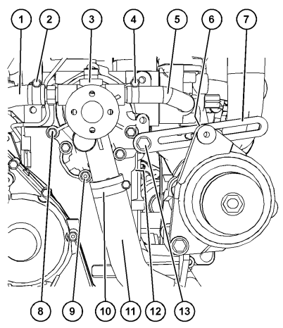
1 Clean very dirty cylinder head covers (1) prior to removal.
2 Remove screws (3, 4) with washers (2, 5).
3 Take off cylinder head cover (1) with Oring (6) from cylinder head (7).

MTU 12V 4000 Cylinder Head Cover Removal and Installation Guide


Installing cylinder head cover
1 Clean mounting surface.
2 Check O-ring (6) for damage, replace if necessary.
3 Coat O-ring (6) with grease.
4 Position O-ring (6) in groove of cylinder head cover (1).
5 Fit cylinder head cover (1) on cylinder head (7).
6 Install cylinder head cover (1) with screws (3, 4) and washers (2, 5).

Posted on

How to Use SerDia2010 to Change Low Idle for Deutz EMR3

How to Use SerDia2010 to Change Low Idle for Deutz EMR3 (1)

Here is the illustration show you guide on how to use Deutz SerDia2010 to change low idle parameter for Deutz EMR3.


Preparations:

2023 Deutz Serdia2010

Deutz DECOM Diagnostic Kit


It is provided for using this function, that the engine is operating in min-/max-governor or allspeed-governor mode (f.e. not fixspeed).

How to Use SerDia2010 to Change Low Idle for Deutz EMR3 (1)

SerDia reads out the actual values of idle run and copies them into the labels in the sub array on the left hand side. This values will be saved further, too.
In parallel a tachometer operates on the right hand.
The actual setpoint value and the actual rotating speed are shown,each as a decimal value below the tachometer and also with indicator and hysteresis region.
Button “read data from ECU”:

How to Use SerDia2010 to Change Low Idle for Deutz EMR3 (2)

went back to previous value of idling speed, which was acquired at the start of the UseCase.
Button”store in ECU”:

How to Use SerDia2010 to Change Low Idle for Deutz EMR3 (3)

writes all variables for idle speed back into the ECU.
If the engine is still running, SerDia will offer to stop the engine automatically, so that the programming of the ECU can take place.

text box “new value”:

How to Use SerDia2010 to Change Low Idle for Deutz EMR3 (4)

An input into this text box has to be confirmed by ENTER.
After that, SerDia changes all variables for idle speed and switches over to working
page, so all changes will be activated in realtime.


Notice:The input is limited for a speed range of 600 – 1200 1/min.