Posted on

How to Install WinPcap for CAT ET 2023A Diagnostic Software

How to Install WinPcap for CAT ET 2023A Diagnostic Software (1)

WinPcap is the third-part tool that allows application to log network communications.This service tool uses it for troubleshooting purposes to log communication exchanges between the service tool and the ECM.If WinPcap is not installed,the service tool can not log this information and it will adversely affect troubleshooting.


If WinPcap is not installed at this time,it can be installed later directly from the WinPcap website.

During the installation of Cat ET, the user will be prompted to install WinPcap. Follow the prompts for the installation.

Note:This will only occur if Cat ET or an earlier version of WinPcap has not been installed.


Preparation:
CAT ET 2023A Diagnostic Software

Caterpillar Diagnostic Adapter 3


How to Install WinPcap?

Step 1: Click “Yes.”


Step 2: Click “Next>” to allow the wizard to guide you through the installation.


Step 3: Read the WinPcap end users license agreement and click the “I Agree” button.


Step 4: Verify that the box allowing the WinPcap driver to automatically start at the boot time is checked.
Then click the “Install” button at the bottom of the dialog box.

How to Install WinPcap for CAT ET 2023A Diagnostic Software (4)


Step 5: Click the “Finish” button to finish the wizard setup of WinPcap.

How to Install WinPcap for CAT ET 2023A Diagnostic Software (5)

Posted on

Bendix EC-60 & EC-80 Dashboard Brake Lamp Test Guide

Bendix EC-60 & EC-80 Dashboard Brake Lamp Test Guide

This instruction show you guide on how to do dashboard brake lamp test for Bendix EC-60 and EC-80 by JPRO diagnostics.


Preparations:

Noregon JPRO DLA+ 2.0 Adapter

JPRO 2023 Diagnostic Softare

The Dashboard Brake Lamp test is available on:
✓ All Wabco braking systems except the mBSP

✓ Bendix EC-60 and EC-80 braking systems.
This test provides the ability to test the dashboard warning and information lamps related to the braking system.
1. Select Dashboard Lamp Tests and press Enter or press Start Button.
2. The Dashboard Lamp Test dialog will be displayed.

Bendix EC-60 & EC-80 Dashboard Brake Lamp Test Guide

NOTE: If lamp status of a lamp is not available, the lamp test for that corresponding lamp will be disabled.
3. Click the button under the desired lamp. Observe the light change on the truck dashboard. Repeat for all lamps
of interest.
4. When done, press the Exit button to return to the test selection dialog.

Posted on

PCC1302 Command Code 155 Intake Manifold Temperature High Shutdown

PCC1302 Command

PCC1302 Command controller engine intake manifold temperature has exceeded 203° F (95° C) for greater than 10 seconds.It set fault code 155,intake manifold temperature high and machine shutdown,here show how to solve it.

PCC1302 Command

2023 InPower 14.5 Service Tool Diagnostic Software+INCAL 2023.06

Cummings INLINE6 Diagnostic Kit


Possible Causes:
1. High ambient temperature
2. Radiator blocked
3. Louvers are closed or damaged
4. Charge air cooler fins or radiator fins are damaged or obstructed
5. Fan belt is broken or loose
6. Fan drive or fan controls are malfunctioning
7. Inaccurate coolant temperature sensor
8. Fault simulation feature is enabled
9. Incorrect threshold setting

Diagnosis and Repair:
1 High ambient temperature
a Using thermocouple verify air temperature entering intake louver of generator.
b Reduce loads or recirculation of discharge air to generator in elevated ambient.

2 Radiator blocked
a Inspect radiator for debris or blockages.
b Remove blockage or winterfront as applicable.

3 Louvers are closed or damaged
a Inspect louvers for proper operation.
b Repair or replace if damaged.
c Check louver motor for proper operation.
d If louver motor is operational, verify louver shutter thermostat is operational


4 Charge air cooler fins or radiator fins are damaged or obstructed
a Inspect for dirt, debris or obstructions.
b Clean if necessary.

5 Fan belt is broken or loose
a Inspect for dirt, debris or obstructions.
b Clean if necessary.

6 Fan drive or fan controls are malfunctioning
a Inspect for dirt, debris or obstructions
b Clean if necessary.
7 Inaccurate coolant temperature sensor
a Use a thermocouple or similar device to measure coolant temperature near sender and compare to coolant temperature displayed.
b Verify the temperature sender resistance and compare to specifications called out in the engine manual.
c Verify continuity from temperature sender wire to engine ECM. Harness resistance should be less than 5 Ohms.
d Repair or replace faulty components or wiring.

8 Fault simulation feature is enabled
a Use the service tool to connect to the engine ECM and verify fault override toggle is disabled.
b Reconfigure generator and disable fault overrides.

9 Incorrect threshold setting
a Use the service tool to connect to the engine ECM and verify fault threshold settings and compare to the specifications called out in the engine manual.
b Verify ECM and PCC calibration number and revision is correct.
c Recalibrate the engine ECM to reset the threshold settings.

Posted on

Volvo EC180 Electric Leakage Oil Filter Element Replacement

Volvo EC180 Electric Leakage Oil Filter Element Replacement

After 1000 hours working,if you Volvo EC180 electric oil filter element leaking,you need replace,here comes the guide.


Related Contents:

Volvo PROSIS 2023

Volvo Techtool Diagnostic Software

Volvo VOCOM 88890300


Notice:

Take care of filters, oils and liquids in an environmentally safe way.


Procedures:

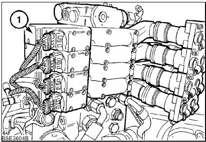
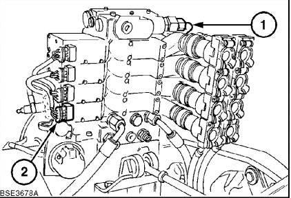
1.Unscrew the leakage oil filter cap (1).

Volvo EC180 Electric Leakage Oil Filter Element Replacement

Figure 1

Leakage oil filter

1Leakage oil filter cap

2Filter element


2.Take off the filter element (2).

3.Check the filter element for dirt and large particles.

4.Inspect the filter element and the filter housing for mechanical damage.

5.Clean the leakage oil filter cap (1).

6.Install a new filter element (2).

7.Install and tighten the leakage oil filter cap.


NOTE!

Tightening torque: 8 Nm (5.9 lbf ft)

Posted on

How to Use CAT ET Diagnostic Software ECM Configuration Function?

CAT ET 2023A (4)

The Configuration function allows configurable information on all available ECMs to be viewed and changed.

CAT ET 2023A (4)

Preparations:

CAT ET 2023A

CAT Communication Adapter 3


Accessing

The Configuration function may be accessed up to three ways:

  1. Select “Configuration” from the Service menu.
  1. Press F5 if the default function keys are set
  1. Click the Configuration Tool icon if the default is set.

Screen Layout

The Configuration screen has the following areas:

Tree Area

The tree area is located on the left side of the screen. The names of each ECM on the data link are listed under the Available ECM(s) folder. Configuration Groups are listed under each ECM.

To view an individual group of parameters, click on one of the Configuration Groups. The selected Configuration Groups parameters will appear in the display area.

Display Area

The display area is located on the right side of the screen. To view a group of parameters, click on the plus [+] symbol to the left of a selected Configuration Group. The corresponding configuration parameters will be expanded.

Note: Information in both the Tree Area and Display area can be accessed using the arrow keys on the keyboard. Use the “Up” and “Down” arrows to move up and down the grid. Use the “Right” arrow to expand a selected Configuration Group. Use the “Left” arrow to collapse the group.

Note: The Configuration function has “mouse over” functionality. As the cursor hovers over the Configuration Group in either the tree or display area, the parameters within that Configuration Group are displayed in a pop up box.

The Configuration display area includes the following columns:

  • The Description column provides the name of the parameter set to configure. Icons that display in front of the parameter name give addition information about the parameter:
    • Require Factory Passwords
    • Locked through the Parameter Lockout function
    • Require Customer Passwords
  • The Value column displays the status of the current parameter
  • The Unit column displays the configuration parameter units.
  • The TT column displays the list of total tattletales. Tattletales represent the number of times a configuration value is changed. Note: For some products, Total Tattletales (TT) is not supported and will not be displayed.

Buttons

The buttons available in the Configuration screen are:

Change Click this button to change the value of a selected configuration parameter value.

Note: This button is only enabled when a configuration parameter can be modified. For some parameters, a valid parameter range is included under the current value.

Note: Depending upon the configuration parameter selected, one of the following dialog boxes will be displayed:

  • Change Engine Power Rating
  • Change Parameter Value
Expand All Click this button to display all of the parameters in each Configuration Group for a selected ECM.

Note: This button is only enabled when an ECM has been selected from the tree area. Only one ECM can be expanded at a time.

Note: When printing a Configuration report, only parameters from an expanded Configuration Group will be included in the Configuration Report File.

Collapse All Click this button to collapse all of the displayed parameters in each Configuration Group for a selected ECM.

Note: This button is only enabled when a Configuration Group has been expanded.


Note: For some products, the Details button is also available. Clicking this button allows the user to view more details about a supported configuration.

Note: The Find function can be used to find a parameter or any word in a parameter in the Configuration screen.

Posted on

How to Use JPRO to do Battery Voltage Test on Bendix

How to Use JPRO to do Battery Voltage Test on Bendix

This instruction show you guide on how to use JPRO Diagnostics software to do battery voltage test for Bendix EC-60 and EC-80.


Preparations:

JPRO 2023 Diagnsotic Software

JPRO DLA+ 2.0 Kit


The Battery Voltage Test is available on:
✓ Bendix EC-60 and EC-80 braking systems
This test checks the health of the battery by measuring voltage levels under loaded conditions.

Procedures:

1.Select the Battery Voltage Test and press Enter or the Start button.
2.The test dialog will be displayed.

How to Use JPRO to do Battery Voltage Test on Bendix

3.Select the Start button to begin the test. Multiple braking system valves will be actuated at the same time to increase load on the electrical system. Vertical lines will appear on the graph to indicate the start and end of the test. Observe the graphed battery voltage.
NOTE: The parking brake must be set before running this test. Simultaneous actuation of the braking system valves can cause the vehicle to freely roll during test duration.
4.Select the Stop button at any time to stop the test. The test will automatically stop after a few seconds.
5.When done, press the Exit button to return to the test selection dialog.

Posted on

How to Avoid New Holland CX8000 AutoCommand Data Loss

This service manual show you guide on how to avoid New Holland CX8000 AutoCommand display data loss.


T7000 Power Command™ TIER 3 – T9. – Variable Chamber – Precision Land Management – FR Forage Cruiser series – 9000 L – CX5000 series Tier IV – T7. Tier 4B – T7.230-260 PowerCommand Classic T4B – T8. SmartTrax™ – T8000 – Fixed Chamber – CX5000 Elevation series Tier IV – CX6000 Elevation series Tier IV – T7.170-210 AutoCommand™ – T7.230-260 PowerCommand Sidewinder II T4B – T7000 AutoCommand™ TIER 3 – T9000 – Large BigBaler series – FR9000 – CX8000 series TIER 3 – CX5000 Elevation series Tier III – CR9000 Tier III – T6. AutoCommand™ TIER 4B (FINAL) – Guardian™ Combo – Guardian™ front boom – 9000 X – VL 6000 – CX6000 Elevation series Tier III – CR Model Year 2016 – CL6000 – T6000 – T7. – T7.220-260 Power Command™ – T8. – FR – T6.120-175 – T6.125-180 TIER 4B (FINAL) – T7. AutoCommand™ Tier 4B – T7.170-210 Range- /PowerCommand™ – T7.230-270 AutoCommand T4B – CX8000 Elevation – CR Harvest Suite Ultra Cab – CR Series Tier IV – CX5000 series Tier III – CX6000 series Tier IV – CX7000 Elevation series – CR series Tier III – Large – Large BigBaler series NA – Guardian™ rear boom – CX Harvest Suite Ultra Cab – CX8000 series Tier IV – 9000 M – T6. AutoCommand™ – T7.220-270 AutoCommand™


Related Contents:

2023 CNH EST

CNH DPA5 Diagnostic Kit

CNH eTimGo Offline


To avoid the loss of data from the IntelliView™  NEW HOLLAND recommends you to follow each of these steps:

Allow the display to shut down completely before you turn OFF the battery isolator switch of the vehicle.

Always use the  NEW HOLLAND approved Universal Serial Bus (USB) Memory stick (Part Number: 84398840) in the display for data storage.

Upgrade the display software application to V30 from EST V8.3.0.0 or higher.

At the end of each working day, archive the information from the USB memory stick to your desktop computer.


Shut down of the display:

Normally when the operator switches the ignition switch OFF, the IntelliView™ display continues to store the display data over a short period of time. If during this storage time the battery isolator switch is also turned OFF, the current display data will be lost.

NOTE: In this situation there is also the possibility that previously stored display data can be lost.

How to Avoid New Holland CX8000 AutoCommand Data Loss (1)


To avoid diplay data losses remember:

Turn OFF the ignition key and then WAIT for 30 seconds before you turn OFF the battery isolator switch.

USB device:

The use of a Universal Serial Bus (USB) memory stick will also help to avoid display data losses.

The continuous use of a USB in the USB port of the monitor:

Ensures that display data is stored to the USB memory stick

Ensures that previous task data are not lost in the event of a premature turn OFF of the battery isolator

NOTE: In the event of a premature turn OFF of the battery isolator only the current task data will be lost. Current task data is the task data since the ignition key was previously switched ON.

NOTE: ONLY use the  NEW HOLLAND USB memory stick 84398840 . DO NOT use any other type of USB memory stick.

How to Avoid New Holland CX8000 AutoCommand Data Loss (2)


Installation of the USB memory stick:

1Insert the USB memory stick into the USB port on the back of the display. Make sure that you fully locate the USB memory stick into the USB port.

NOTE: You MUST insert the USB memory stick into the USB port, before you turn the display ON. If you insert the USB memory stick into the USB port after you turn on the display, the system DOES NOT detect the presence of the USB memory stick.

NOTE: To avoid display data corruption, NEVER remove the USB memory stick until the display is completely powered-down. For complete shut down of the display, wait for 30 seconds after you turn the ignition OFF.

How to Avoid New Holland CX8000 AutoCommand Data Loss (3) How to Avoid New Holland CX8000 AutoCommand Data Loss (4)


From the ‘Display setup’ screen:

3Select ‘Advanced’ from the ‘Interface level’ drop down menu.

NOTE: This action will restart the display. When the display restarts, the display will automatically recognise the presence of the USB memory stick.

How to Avoid New Holland CX8000 AutoCommand Data Loss (5)


4Turn the ignition switch OFF to shut down the monitor.

NOTE: The first time that the monitor is shut down you will notice that the initial shut down takes more time than usual. During this initial shut down, there is the transfer of all the previous task data onto the USB stick.

NOTE: If you need to remove the USB stick, only do so after the monitor has completely shut down.

V30 Display Software Upgrade:

Prior to the release of V30 display software, the display data would continuously record to the USB memory stick during machine operation

In machine applications with heavy data transfer, for example ‘Yield Monitoring’ or use of the ‘As Applied’ application, this heavy data transfer can result in:

Premature USB device failure

Display Data Corruption

The display rebooting or crashing

NOTE: The new logic in the V30 display software greatly reduces the risk of occurrence of the three above issues.

Since the release of the V30 display software, the display data transfers to the internal memory of the display during machine operation.


CNH EST Diagnostic Software


The display data within the internal memory of the display then transfers onto the USB memory stick when:

The operator shut down the display

The operator selects a new grower name, farm name, or field name

NOTE: This data transfer applies for both the CNH proprietary ‘Voyager’ display format and for the ‘Task Controller ISOXML’ format.

For full information with regard to software downloads see the:

IntelliView™ Service Manual: Software – Program

Archiving Display Data:

At the end of each working day,  NEW HOLLAND recommends you to archive the information from the USB memory stick to a desktop computer. This action should be common practice for all vehicles that incorporate IntelliView™ display systems.

Posted on

Jungheinrich ETM/V 13,5-20 MSEseries Forklift Hoist Frame Tilting Mechanism Checking and Adjusting

This instruction show you guide on how to check and adjust the hoist frame tilting mechanism for Jungheinrich ETM/V 13,5-20 MSE series forklift truck.

Jungheinrich JETI Judit-4 v4.37.001

Jungheinrich JETI SH 4.36 Forklift Service Information 2023

Jungheinrich JETI ET 4.37 EPC Updated 492 Spare Parts Catalog


Checking and adjusting the hoist frame tilting mechanism
1 Checking and adjusting hoist frames equipped with fork tilting systems1.1 lllustration/table of adjusting dimensions

1.2 checking the hoist frame tilt-back
NOTE: Hoist frame tilt-back checking and adjusting operations must be performed without anyload on the fork.
– Place the vehicle on level ground, rotate the drive wheel through 90° andapply the parking brake.
– Move the hoist frame tilting system forward against the stop.
– Attach a plummet to the fork carrier and raise the fork to a height of 1000 mm.
– Let fall a perpendicular from a lifting height of approx.1000 mm and mark the first measuringpoint on the ground.
– Raise the hoist frame together with the plummet to the full lifting height “h?” and lower thefork by 30 mm.Let fall a perpendicular and mark the second measuring point on the ground.- Check that the dimension between the first and second measuring point corresponds with theadjusting dimension “X” (mm) indicated in the table for the lifting height “hg”.
Readjustment of the tilt-back is necessary when the Xmin / max -values indicated in the tableare exceeded!

1.3 Adjusting the hoist frame tilt-back
– Slacken nut (1) of the vibration damper and check nut(3)(left-hand thread) and clampingscrews (2) of the mast blocking device.
– Rotate the middle section (4) of the mast blocking device in the required direction until theadjustment dimension “X” , relating to the lifting height “h,” as indicated in the table, has beenobtained.

NOTE: When looking in the direction of the check nut (3):
– Clockwise rotation of the middle section (4) of the mast blocking device will increase theadjustment dimension “X”
-Anti-clockwise rotation will reduce the adjustment dimension “x”.
– Check nut (3) and clamping screws (2) thighten using the required torque.
– Proceeding as detailed in para.1.1 , raise and lower the hoist frame twice between the first andsecond measuring point, each time checking dimension “X” between the markings on the
ground.
Perform the required corrections, if the Xmin / Xmay values, as indicated in the table, areexceeded.
– Tighten nuts (1 ) of the vibration damper.
Block dimension of the spring packet A = 0mm.

Posted on

How to Use JCB ServiceMaster 4 Flashloader Tool

How to Use JCB ServiceMaster 4 Flashloader Tool (1)

The Flashloader software tool is part of the JCB Servicemaster software suite.If the ECU is replaced and the data file in its flash memory is not applicable it will be necessary to `flash’ the ECU memory with the correct data file. The Flashloader software tool can be used to access the data file name
currently loaded in the ECU memory and is necessary up load a new data file ito the ECU.


Related Contents:
Newest JCB ServiceMaster 4 Diagnostic Software

JCB Machine EPC+Service Manual 2017
JCB KG V2 to Unlock Function


Connecting Flash Loader
To use Flash Loader your laptop computer must be connected to the machine CANbus.


Starting Flashloader
1 Turn ON the machine ignition but DO NOT start the engine.
2 Start JCB Servicemaster on the laptop computer.

How to Use JCB ServiceMaster 4 Flashloader Tool (1)

3 Make sure that the correct DLA is selected in the chooser. Click on `Utilities’, DLA Setup. The DLA
Chooser window opens. Check the button to match to the Current Device. Click `Apply’

How to Use JCB ServiceMaster 4 Flashloader Tool (2)

4 Select the required machine range

How to Use JCB ServiceMaster 4 Flashloader Tool (3)

5 The Flashloader tool will then open.


Using Flash Loader
Important: Do not turn off the ignition or isolate the system by accidentally engaging the operators seat isolation switch when using the flash loader. This will interrupt the flash signal to the ECU and will irreparably damage the ECU.
1 Make sure that the machine ignition switch is set to`ON’ but do not start the engine.
2 Click on the ECU icon.
3 Click on the `Browse’ button and select the correct data file. Click `Open’.

How to Use JCB ServiceMaster 4 Flashloader Tool (4)

4 Click on the `Start’ button. A confirmation window will appear. Click on the `Yes’ to start the reprogramming of the ECU. The progress bar is displayed.

How to Use JCB ServiceMaster 4 Flashloader Tool (5)

5 When the programming is complete switch the machine ignition to the `OFF’ position.
Important: Re-flashing the engine ECU changes the base programme. Re-flashing the ECU does not configure the machine settings such as fuel injector calibration codes,and other machine specific options.
6 Before starting the engine make sure that the machine setup data is correct. You must check that all other relevant machine settings are correctly configured. Use the setup software tool.

Posted on

How to Solve Caterpillar Communication 3 142 Hardware not responding Error

142 Hardware not responding Error

When you connection Caterpillar Communication 3 adapter to machine and PC,sometime you will get 142 hardware not responding error.Here comes solutions.There are several possible causes of a Error 142 “Hardware not responding” message.

142 Hardware not responding Error

CA3 driver installation error

First, ensure the CA3 is plugged into the USB port on the PC. Next, perform the following steps to ensure that the CA3 drivers are properly installed:

Click Start.

Access the Device Manager:

Right click on the Start Menu icon and select Computer Management from the list. The Computer Management dialogue window will open. Select Device Manager, located in the left column.

Click on “Vehicle Data Link Adapter” and the “CAT Comm Adapter 3” option should appear. A red X should not be shown over the icon in front of the name. If there is a red X over the icon, then reinstall the CA3 driver.


The CA3 Toolkit is running

The CA3 Toolkit will monopolize communication to the CA3, and no other application will be able to communicate with the CA3. Shut down the CA3 Toolkit in order for the service tool to communicate.


Internal Power Supply is active

CA3s built in 2009 generated electrical noise from the built-in USB power supply, which was problematic for some PCs. In these instances, the CA3 would not be detected by the service tool or by the CA3 Toolkit. See the “Turn off CA3’s internal USB power supply” recommended practice in order to address this issue


CA3 is not properly powered

When the CA3 powers up, the LED lights on the front of the device glow and then will sequentially turn off from the top (“Data Link” end) to the bottom (“Computer”end) of the device. The Power LED will turn color from orange to red and then the blue “USB” LED will blink once. The CA3 will not be operational until this sequence has occurred. The sequence can take up to 10 seconds.


CAT ET 2023A