Posted on

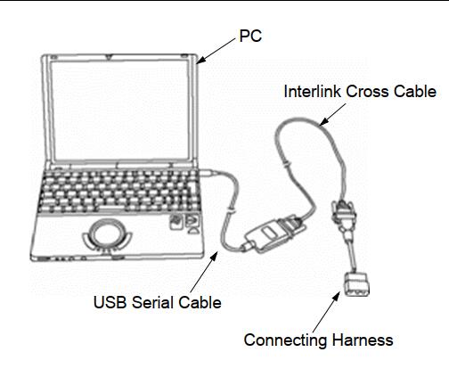
Bobcat Engine P2B8C/P2B8D DEF Pump Motor Internal Duty Low/High

Bobcat Engine P2B8C/P2B8D DEF Pump Motor Internal Duty Low/High-2

1) Overview

U004375-24

1 Electric problem (Supply module connector)
2 Electric problem (Wiring harness DCU to supply module, Supply module)
3 Electric problem (DCU connector, DCU)

Bobcat Engine P2B8C/P2B8D DEF Pump Motor Internal Duty Low/High-1


Related Contents:

Service Analyzer 91.15 for Bobcat Diagnostic Software

2023 Bobcat Engine Analyzer ECU DCU Diagnostic Software


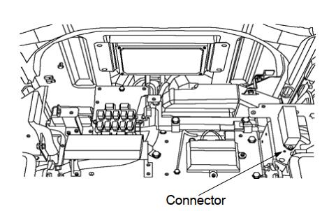
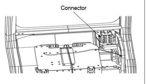
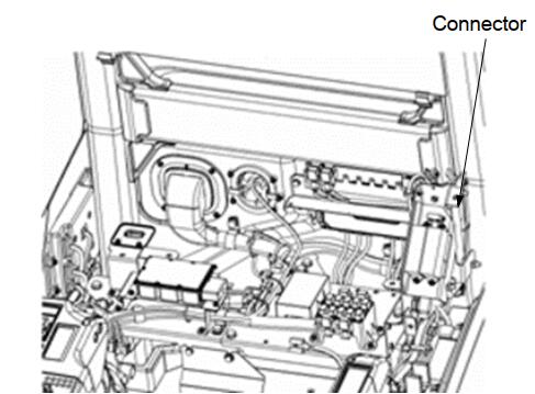
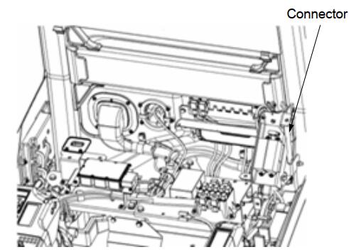
2) Component Location

Bobcat Engine P2B8C/P2B8D DEF Pump Motor Internal Duty Low/High-2


3) Condition for Running Diagnostic
When pump motor is normal
4) Condition for Setting the Fault Code
When the sensor value (raw duty cycle) is less than 4%
5) Condition for Clearing the Fault Code
When the sensor value (raw duty cycle) is greater than 4%
6) Check List

Step Inspection Standard
Value
YES NO
1 P2B8C/P2B8D is occurred on diagnostic tool? Step 2
2 After let the machine be in safety area and turn
off the key switch
Step 3
3 Check sensor connection
Connection problem?
Do necessary
repair
Step 4
4 Check DCU connection
Connection problem?
Do necessary
repair
Step 5
5 Check the DCU voltage related pin connection and
harness.
Pin or connection problem?
Do necessary
repair
Step 6
6 Check continuity and electrical insulation
Electrical problem?
Fix harness Change SM


Posted on

Deutz TIRE4 Engine SCR Service Routines by SerDia2010

Deutz TIRE4 Engine SCR Service Routines by SerDia2010 (1)

Deutz TIRE4 Engine SCR Service Routines by SerDia2010 (1) Deutz TIRE4 Engine SCR Service Routines by SerDia2010 (2)


1 Pressure test
While pressure test with a stopped engine the DEF pump is regulated at 9 bar. The test is
used to check the pump components to their function. The test involves no automatic
evaluation and must be actively terminated. It is to verify that the system controls on 9 bar
and this pressure is retain.


2023 Deutz Serdia2010

Deutz Diagnostic Kit


Deutz TIRE4 Engine SCR Service Routines by SerDia2010 (3)

2 Injection Test
At the start of injection testing first the DEF pressure is built up. Then a definite amount
DEF is injected. The test is used to check both, the pump module and the function of the
dosing module.
The dosing module must be removed for this test.


Deutz TIRE4 Engine SCR Service Routines by SerDia2010 (4)

3 The service “empty lines” must be accomplished after a service routine is completed, that the DEF lines can be emptied after ignition change.
(This is not necessary for the EOL-test or the service regeneration)

Deutz TIRE4 Engine SCR Service Routines by SerDia2010 (5)


SCR-Heater relay activate
Setting of the individual heating relay to check the customer’s wiring.
– DEF Heater Main-relay
– DEF Heater Suction line
– DEF Heater Pressure line
– DEF Heater Back flow
– electrical heater – Supply Modul
– tank heater relays (coolant water)

Deutz TIRE4 Engine SCR Service Routines by SerDia2010 (6)

After changing the SCR Catalyst the service “SCR Cat changed” must be set.

Deutz TIRE4 Engine SCR Service Routines by SerDia2010 (7)

inducement counter reset
The exhaust legislature requires that emission-related defects, provided they bear a
permanently,enable a power reduction.
Current derating must be reset after repairing/troubleshooting by the service tool.
The button appears only in Serdia2010 when the power reduction is active.
After the counter has been reset, the button disappears.


Posted on

Scania Truck Alarm System Wake-up Signal Short-circuit Solution

Here is the instruction show you guide on how to solve Scania truck Alarm system Wake-up signal short-circuit to ground.


Preparations:

Scania SDP3 2.60.1 Truck Diagnostic Software

Scania Multi EPC 2024.03

Scania VCI3 High quality


Wake-up signal for Scania Communicator, short circuit

Error identification

Wake-up signal for Scania Communicator is short-circuited to ground.


Cause

Fault in harness-to-component connectors or cable harness for the wake-up signal for Scania Communicator.

Internal fault in ALM control unit E7.

Notes

Symptom

The alarm system cannot initiate Scania Communicator.


Action

Disconnect the harness-to-component connector to ALM control unit pin A5.

Measure for short circuits throughout the cable harness.

If there are a number of harness-to-component connectors between the wake-up signal and the ALM control unit, disconnect them and measure in order to isolate the fault.

If the fault is not in the cable harness it is probably an internal fault in ALM control unit E7.

Posted on

Volvo MACK EPA07 Engine Flow Test Injector Activation by JPRO

Volvo MACK EPA07 Engine Flow Test Injector Activation by JPRO

Aftertreatment Injector Activation for Flow Test is supported on:
✓ Mack and Volvo EPA 07 engines.


Related Contents:

JPRO Noregon Commercial Fleet Diagnostics 2024

Noregon JPRO DLA+ 2.0 Adapter


The Aftertreatment Injector Activation for Flow Test activates the injectors to test flow.
1 Select Aftertreatment Injector Activation for Flow Test and press Enter or the Start button.

2 The test dialog will be displayed.

Volvo MACK EPA07 Engine Flow Test Injector Activation by JPRO

3 Select the Start button to begin the test.
4 Activation of the aftertreatment injector should result in a “click” sound. Monitor the displayed data values.
5 Select the Stop button to stop the test.
NOTE: To prevent damage to the engine, the test will automatically stop after 30 seconds.
6 When the test has completed, click the Exit button to return to the test selection dialog.

Posted on

HINO J05E Engine 2018 VNT Actuator Initialize Error P003A Solution

This instruction show you guide on how to solve HINO J05E Engine 2018 VNT Actuator Initialize failure.


Related Contents:

HINO DX3 Diagnostic Software

NEXIQ USB LINK2


Technical Description:

1) The VNT actuator moves the nozzle vane steplessly by the LEA (Linear Electric Actuator) to control the turbo speed and boost pressure.

2) The LEA has a sensor to detect the movement of the actuator, always monitoring the reading and actual value of the nozzle vane opening.

3) Wiping operation is performed while the engine is stopped for the purpose of removing soot and oil coming out from the range of vane operation and checking the turbo mechanical operating range for abnormality.


DTC Set Condition:

1) DTC Detection Condition:

  1. a) Starter key “ON”.
  2. b) The battery voltage is in the range of 10 to 16 V.
  3. c) The engine is stopped, or the engine speed remains at 500 r/min or more for 5 seconds or more.

2) Judgement Criteria:

  1. a) Initialization failure – When the amount of operation after power has been turned ON is larger than HI range, or when the Hall IC output does not become constant after 5 seconds has elapsed


Reset Condition:

1) After normal operation is restored and the starter key is turned “LOCK”.


Indication, Warning or System Control Regulation When The DTC Is Set:

1) MIL: ON

2) SVS light: OFF

3) Engine output is restricted.


Symptoms On The Vehicle The DTC Is Set:

1) Symptoms On The Vehicle Due To Backup Control (Fail Safe Function):

  1. a) Engine output is insufficient.

2) Symptoms On The Vehicle Due To Malfunction:

  1. a) None


Pre-Inspection Work:

1) Check that the battery voltage is in the normal range.


After-Inspection Work:

1) Clear all past DTCs.

2) Check that no DTC is detected after test drive.

Possible Causes:

1) VNT link is stuck or cannot operate due to rust, etc.

2) External link is disconnected.

Posted on

Volvo All Engine Actuator Supply Voltage “A” P065713 Solution

The following components are connected to a common 12V supply

1) A138: DEF Direction valve

2) A138: Aftertreatment Diesel Exhaust Fluid (DEF) Pump Motor

3) Y81: Aftertreatment Diesel Exhaust Fluid (DEF) Tank Heater Valve

If an abnormal voltage or current is detected on the common supply a DTC is set

Volvo All Engine Actuator Supply Voltage “A” P065713 Solution

Related Contents:

[03.2024] Volvo Techtool PTT 2.8.241+ACPI 0.7.1.0 High Level+Devtool

Volvo Vocom

Volvo PROSIS 2024


Conditions for diagnostic trouble code (DTC):

1) Open circuit

Observable symptoms

1) None

Probable cause

1) Wiring harness

2) Connector

3)A138: DEF Direction valve

4) A138: Aftertreatment Diesel Exhaust Fluid(DEF) Pump Motor

5) Y81: Aftertreatment Diesel Exhaust Fluid(DEF) Tank Heater Valve

6)A137: Aftertreatment Control Module (ACM)

Posted on

How to Use SerDia2010 Perform EGR Actuator Test for Deutz Engine

This instruction show you guide on how to use SerDia2010 diagnostic to do EGR actuator test for Deutz engine.


Preparations:

2023 Deutz Serdia2010 v14.1.9.1 Diagnostic Software Free Download

Deutz Diagnostic Kit DECOM for Deutz Engine


Procedures:

The Button does not appear with The software P_802_680_640_005.

This test is designed for the if the EGR actuator motor has been replaced, the end position of the EGR actuator easy and simple
can be calibrated and stored in the ECU.
To run the EGR actuator reset open the corresponding use case in SerDia2010 as shown in the lower Image.

Once the Use-Case has started the test can be started directly by clicking on the
Button “EGR actuator reset” (pictured purple highlighted).

If the EGR reset is active, next to the selected button (in the lower purple marks) a
rotating icon appear.

If the EGR controller reset was successful, SerDia shows the message below.

Notice:This function is available at Competence Class 2.

Posted on

CASE IH 20 Series Combine Bleeding Service Break Operation

CASE IH 20 Series Combine Bleeding Service Break Operation (1)

CASE IH agriculture 7120-9120 series axial-flow combine bleeding service break operation guide.


The European machines may be equipped with a pressure limiting valve to prevent the main drive wheels from locking up. The valve incorporates a solenoid L-32 that when activated will expose the brake pressure lines to a relief.

CASE IH 20 Series Combine Bleeding Service Break Operation (1)


Related Contents:

CNH DPA5 Diagnostic Kit

CNH EST 9.10 Diagnostic Software

CNH eTimGo Repair Manuals


Any time the brake is disassembled or lines removed, the system will require bleeding. To bleed the system proceed as follows:

REMEMBER: As the brake pedal must be depressed several times while bleeding,this job has to be done with two persons.
CASE IH 20 Series Combine Bleeding Service Break Operation (2)

Procedures:

1 Park the combine on level ground and block the wheels adequately to prevent the combine form rolling. The engine does NOT need to be running.
2 Raise the header and engage the header safety latch. Stop the engine.
3 Verify that the brake reservoir is filled.
4 Slide a transparent hose over the RH outside bleed screw to catch the oil when bleeding.
5 Cab Operator holds down the LH brake pedal and pumps RH brake pedal.
6 Bleed Operator loosens RH outside caliper bleed valve (#1 in photo) to allow the air to bleed out, and then retightens it when oil comes out of the port.
7 Operator then loosens RH inside caliper bleed valve (#2 in photo) to allow the air to bleed out, and then retightens it when oil comes out of the port.
8 Operator in cab then holds down RH brake pedal and pumps LH brake pedal.
9 Repeat steps 5-7 for the LH side.
10 Check for the reservoir for proper oil level


Posted on

Caterpillar C9 Engine PTO Engine Shutdown Switch Voltage Low

Caterpillar C9 engine PID 186-4 PTO engine shutdown switch voltage low solution.

Caterpillar C9 Engine

Caterpillar CAT ET 2023C

CAT Comm Adapter 3


A short to ground exists in the wiring for the PTO engine shutdown switch. The parameter “PTO Engine Shutdown Switch” must be programmed to “J1/P1:7” or “J1/P1:23”.


If the vehicle speed is not equal to zero, or if there are active vehicle speed faults, the engine will go to low idle. The engine will not shut down when the vehicle speed falls to zero. When the PTO engine shutdown switch is pressed, a 186-14 will become active. The code will stay active until the engine shuts down. When the engine shuts down, the code will be loggged.


Possible Causes:

1) ECM Connection/Harness

2) PTO Shutdown Switch Failure

3) ECM Failure

4) Wiring between PTO shutdown switch and ECM

Posted on

Perkins 1106D EPG Engine CID 0172 FMI 04 Trouble Code Solution

Perkins 1106D EPG Engine CID 0172 FMI 04 Trouble Code Solution

Autoepccatalog.com show the instruction on how to solve Perkins 1106D Electric Power Generation CID 0172 FMI 04 trouble code.

Perkins 1106D EPG Engine CID 0172 FMI 04 Trouble Code Solution

Related Contents:

Perkins Communication Adapter 3 27610402

Perkins EST 2023A

Perkins SPI2 2018A Service and Parts Catalogs


Conditions Which Generate This Code:
The Electronic Control Module (ECM) detects the following conditions:

• The signal voltage from the intake manifold air temperature sensor is less than 0.2 Volts DC formore than eight seconds.
• The ECM has been powered for at least two seconds.
• Diagnostic code 0168-01 is not active.

System Response:
If equipped, the diagnostic lamp will flash. The ECM will log the diagnostic code.
The ECM will use the default value of 70 °C (158°F) for the intake manifold air temperature. “Voltage Low” will be displayed next to the status for “Intake Manifold Air Temperature” on the electronic service tool.

Possible Performance Effect:
• Poor stability
• Poor cold running
• White smoke
• Black smoke
• Poor acceleration under load

Troubleshooting:
This fault can be caused by a sensor that is shorted to ground or a sensor that is internally shorted.
Perform the following diagnostic procedure: “Engine Temperature Sensor Open or Short Circuit – Test” Results:
• OK – STOP