Posted on

Volvo Techtool do Test and Calibration on Volvo Version 2 and Older Truck

Volvo Techtool do Test and Calibration on Volvo Version 2 and Older Truck (1)

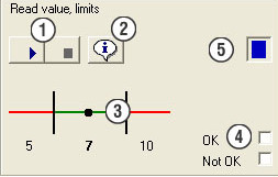
This instruction show you guide on how to use Volvo techtool diagnostic software and VOCOM 88890300 do perform test and calibration for Volvo version 2 and old truck.This section describes the functions available in the window when an operation has been opened. The illustration shows a typical test/calibration operation. When programming, a list of programming parameters is shown in field 5.


What your need?

2025 Volvo Techtool PTT 2.8.310+ACPI 0.7.1.0 High Level+Devtool

Volvo Vocom

Volvo PROSIS 2024

Volvo Techtool do Test and Calibration on Volvo Version 2 and Older Truck (1)


Toolbar

The following function buttons are available in the toolbar.

Information text – click the button to display/hide the text and image field.

Close – click the button to stop an operation and return to the previous view. Alternatively, use the Esc key.&nbsp

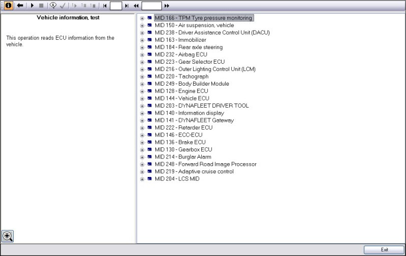
Open – click the button to open an operation.

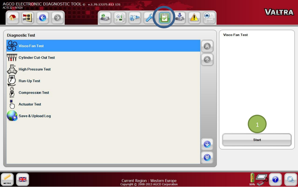
Start – click on the button to start the current operation, or use Ctrl + Space Bar.

Stop – click on the button to stop the current operation, or use Ctrl + Space Bar or Esc.

Default information – click the button to display the same information in the text and image field as when the operation was started.

Prerequisites – click the button to display the conditions for the implementation of the operation and the status of conditions.

Start replay – click the button to start playback of the selected operation.

Pause replay – click the button to pause the playback of the operation. Restart the playback by clicking Start replay.

Stop replay – click the button to stop playback of the operation.

Rewind – click on the button to quickly rewind an operation manually.

Previous session – click on the button to jump to the previous session manually.

Next session – click on the button to jump to the next session manually.

Forward – click on the button to fast-forward an operation manually.

Session number – states which session is being played.

Session time – states how far into a session you are.
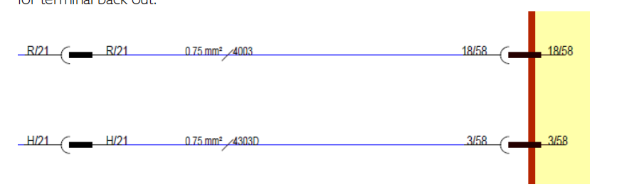
 

Wiring schematics

The wiring schematics shown by clicking on a link in the text field are to be used as a functional description. The schematic shows the conditions that apply when the function is active.

Note: The wiring schematics are not to be used as a basis for circuit measurements.


Cable colors

There are four colors – red, blue, green, and black – used on the wiring schematics

Red is only used for power supply, irrespective of whether it is battery voltage or a supply from a control unit (for example, 5 V).

Blue is used for wires connected to a grounding point even if they are indirectly connected, i.e. via a control unit.

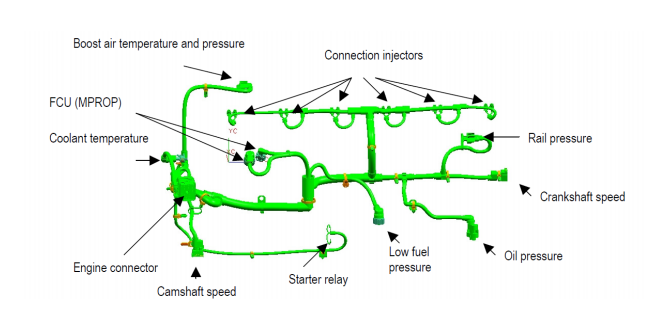
Green is used for signal cables, primarily to indicate the signal cable from a sensor.

Black is used where the function of the cable is not relevant or where the cable cannot be categorized according to the other colors.


Checking conditions

Click this button to check the condition’s status. You can check conditions at any time except when the actual operation is being run. If the button is grayed out, there are no conditions for the operation.

Volvo Techtool do Test and Calibration on Volvo Version 2 and Older Truck (2)


Once an operation has been started, the conditions for implementing the operation are checked. In certain cases conditions are checked even after an operation has been exited.

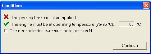
A window containing conditions and their statuses is displayed. The following status markings are available.

Green marking – Condition fulfilled.

Red marking – Condition not fulfilled.

Grey marking – Condition not yet checked

Check box – Condition that must be checked manually: for example, blocked wheel. When a manual check has been carried out the check box must be checked.

In certain conditions, the sensor value on which the status marking is based is displayed.

Click Cancel to cancel the check.


Presentation element

This section gives a general description of the available presentation elements.

Most presentation elements contain the following components.

Volvo Techtool do Test and Calibration on Volvo Version 2 and Older Truck (3)


Posted on

When Fendt 900 Varios Sensors Concerned Must Be Calibrated?

Fendt 900 Varios COM III

Fendt 900 Varios Sensors Concerned compensate for mechanical and electrical tolerances in sensors, the sensors concerned must be calibrated.If a sensor is replaced, it must be calibrated.

Fendt 900 Varios COM III

What Required:

FENDT Fendias v2.2024

AGCO 2×4 CANUSB


The following sensors and functions require calibration

1 Rear EPC calibration (depth control code 8001 and rear power lift position code 8002)

2 Calibration, EPC front (code 9001 and code 9002)

3 Calibration, crossgate lever (hydr. auxiliary valves) (code 1001)

4 Calibration, linear module 1 (hydr. auxiliary control vakve) (code 1003)

5 Calibration, linear module 2 (hydr. auxiliary control vawve) (code 1004)

6 Calibration, linear module 3 (hydr. auxiliary control valve) (code 1005)

7 Calibration, linear module 4 (hydr.auxiliary control valve) (code 1006)

8 Calibration, front axle suspension (code 7666)

9 Steering calibration (steering angle sensor code 2401/Autoguide control valve code 2403)

10 Calibration,rear PTO coupling time (code 6034)

11 Calibration,front PTO coupling time (code 7034)

12 Calibration,drive clutch pedal (code 4001)

13 Calibration,hand throttle pedal (code 2)

14 Calibration, travel range selector (code 4003)

15 Calibration, foot throttle pedal (code 4005)

16 Calibration, transmission ratio characteristic (code 4007)

17 Calibration, turbo-clutch function (code 4009)

18 Calibration, throttle pedal resolution (code 4010)

19 Calibration, heater valve (no code)


NOTE: Observe the calibration sequence.

Calibrations 1 to 11 and 19 can be performed in any order.

Calibrations 12 to 18 must be performed in sequence and en block (transmission calibration).The transmission emergency operation must not be switched on during calibration.(Transmission oil temperature higher than approx.409C during transmission calibration).If incorrect values are detected or the conditions are not met, an ERROR message appears If calibration completes successfully, OK is displayed, and the new sensor settings are stored.Data are only accepted when ignition key is turned to position “0”.(Wait for at least 15 seconds before switching on the ignition again!)

Menu levels on the A007 instrument panel

Posted on

How to Install Left Water Tank for Hitachi HITACHI EX5600 Excavator

How to Install Left Water Tank for Hitachi HITACHI EX5600 Excavator (1)

This instruction show you guide on how to install left water tank for Hitachi EX5600 excavator.


Related Contents:

2024 HITACHI AllinOne Tool 3.13

Hitachi Dr.ZX Excavator Diagnostic Tool Cable

Hitachi Excavator ZX-7 Service Repair Workshop Manual 2021 PDF


CAUTION: The water tank (1) assembly weight:

155 kg (345 lb)

1 Install shackles (4 used) to lifting holes (b) (4 places) of water tank (1). Attach nylon slings onto the shackles (4 used). Hoist and hold the water tank (1) assembly.


2 Install the water tank (1) assembly with bolts,washers (5) (8 used).

j : 19 mm

m : 90 N·m (66 lbf·ft)


3 Connect hoses (3) (2 used) with clamps (2) (2 used).

j : 11 mm

m : 12 N·m (8.9 lbf·ft)


4 Connect connector (4).

How to Install Left Water Tank for Hitachi HITACHI EX5600 Excavator (1) How to Install Left Water Tank for Hitachi HITACHI EX5600 Excavator (2)


5 Connect the both ends of hoses (2) (3 used), hose (4), and hoses (5) (4 used) with clamps (1) (11 used) and clamp (3).

j : 7 mm

m : 8 N·m (5.9 lbf·ft)


6 Secure hoses (2) (3 used), hose (4), and hoses (5) (4 used) with bolts, washers (6) (8 used), clip (9), clamps (7) (4 used), and plates (8) (4 used).

j : 17 mm

m : 50 N·m (37 lbf·ft)


7 Secure hoses (2) (3 used), hose (4), and hoses (5) (4 used) with covers (13) (2 used) and bolts, washers (12) (4 used).

j : 17 mm

m : 50 N·m (37 lbf·ft)


IMPORTANT:Secure hose (5) with clips (11) (2 used) so that hose (5) should not interfere with hose (b).


8 Secure hoses (5) (4 used) with clips (11) (5 used) and bolts, washers (10) (5 used).

j : 17 mm

m : 50 N·m (37 lbf·ft)


9 Install eyebolts (M10, Pitch 1.5 mm) (2 used) to the bolt, washer (6) holes (2 places). Attach nylon slings onto the eyebolts (2 used). Hoist and hold the cover (7) assembly.


  1. Install the cover (7) assembly with bolts, washers (8) (7 used).

j : 17 mm

m : 50 N·m (37 lbf·ft)


11 Install bolts, washers (6) (2 used).

j : 17 mm

m : 50 N·m (37 lbf·ft)


12 Install cover (1) with bolts, washers (2) (5 used).

Install cover (3) with bolts, washers (9) (3 used).

j : 17 mm

m : 50 N·m (37 lbf·ft)


13 Install plates (4) (2 used) with bolts, washers (5) (8 used).

j : 17 mm

m : 50 N·m (37 lbf·ft)

Posted on

Allison 3000 & 4000 Gen5 Output Shaft Speed Sensor Circuit

Allison 3000 & 4000 Gen 5

Here is the instruction show you guide on how to repair Allison 3000 and 4000 Gen5 transmission P0720 Output shaft speed sensor circuit.

Allison 3000 & 4000 Gen 5

Related Contents:

Allison DOC GEN5 Diagnostic Software 2025.02

NEXIQ USB Link 3 Diagnostic Tool


DIAGNOSTIC RESPONSE:

DNS, Lock in current range


CIRCUIT DESCRIPTION:

The speed sensors are devices which convert mechanical motion to an electrical signal. This test detects an output speed sensor circuit short to battery, ground, or open.


ACTION TAKEN WHEN THE DTC SETS:

When DTC P0720 is active, the following conditions occur:

1 If the DTC sets while shift not in process, remains in current range.

2 If the DTC sets while shift is in process, complete shift and lock in that range.

3 There is no response to shift selector requests.

4 DTC is stored in TCM history.

5 The CHECK TRANS light illuminates.

6 The TCM inhibits TCC engagement.

7 The TCM freezes shift adapts.


CONDITIONS FOR CLEARING THE DTC:

Use the diagnostic tol to clear the DTC from the TCM history.The TCM automatically clears the DTC from the TCM history if the vehicle completes 40 warm-up cycles without the DTC recurring.


DIAGNOSTIC AIDS:

DTC P0720 may be caused by:

1 W140 and/or W160 shorted to another wire in chassis harness or to ground.

2 W140 and/or W160 high resistance or open circuit.

3 Broken or defective connector assemblies allowing pushed back pins to short together.

4Unlocked connectors, missing seal plugs allowing moisture in connectors.

5 Fatigued wires at speed sensor connectors (broken strands).

6 Incorrect pin crimps or expanded terminals.

7 Defective output shaft speed sensor.

8 Defective TCM.

9 Wire pair not twisted or not sufficiently twisted.


NOTE:Confirm that the sped sensor wiring consists of twisted pairs at the rate of 12 to 16 twists per 300mm.These twists must extend the entire length of the wiring harness to within at least 50mmof the speed sensor connector.


NOTE:

The OEM Transmission warranty, or the extended cover and mission specifications.

Review applicable information in CONTROL SYSTEM AND TRANSMISSION SPECIFICATIONS to find additional connector diagrams, and troubleshooting tips.

Posted on

How to Solve Deutz EMR3 Charge Air Press 32 / 102 / BPSCD Error

This instruction show you guide on how to solve Deutz EMR3 Charge air press 32/102/BPSCD error.Charge air pressure sensor: the measured voltage of sensor by ECU is out of the target range; the calculated charge air pressure is implausible or the received value via CAN is defective.


Related Contents:

Deutz Serdia 4.0 Diagnostic Software

Deutz DECOM Interface Diagnostic Kit


Error codes

DEUTZ-Errorcode: 32

BlinkCode (short-long-short): 2 – 2 – 3

SPN: 102


Possible FMI:

3: Voltage to high or short circuit to +Ubatt

4: Voltage to low or short circuit to -Ubatt

2: data stream is defective

2: data stream is defective


Error Detection

Error lamp shows permanent light. Entry in error memory.


Possible reason for error

Cable break or short circuit, sensor defective, onnection cable  demaged


Take actions for error repair

Check cabling, if LDF6T sensor not working, check sensor and if

necessary replace it, check connection cable and if necessary repair or replace it

other error properties


System reaction: Warning, substitute value

Behaviour error lamp: permanent light

Self healing: yes

Signal Priority: 4

Measurement @ error time: default value

Posted on

How to Perform Accessing Traction Aid Brake Test for Caterpillar Machine

CAT ET 2025A Traction Brake Test function allows the Step, Bleed, and Ramp tests to be performed on a selected brake line. A brake may be manually turned on and monitored.This instruction show you guide on how to use CAT ET 2025A to do accessing traction aid brake test for Caterpillar machine.


Related Contents:

CAT ET 2025A

CAT Comm 3

Caterpillar 18 digits factory password calculator


Note:The test will not work if the machine speed is over 3 mph. This prevents the brake from overheating.


Accessing

To run the Traction Aid Brake Test, select “Diagnostic Test” from the Diagnostics menu, and then select “Brake Test” from the submenu. The Traction Aid Brake Test screen is displayed.


Screen Layout

The Traction Aid Brake Test screen has the following areas:


Status Parameter Area

There are four status parameter boxes: Left Front Brake Test, Right Front Brake Test, Left Rear Brake Test, and Right Rear Brake Test. Each box includes the following information:

Test Status – Displays the selected test type: Bleed, Ramp, or Step. If a test has not been selected, No Test is displayed.

Current Test Icon – Displays as a visual representation of the selected test.

Desired Pressure Value – Displays as a value measured in PSI (kPa).


Wheel Selection Area

The Wheel Selection area is located in the center of the screen. This area allows the user to select the wheel corresponding with the brake to be tested by clicking the radio button next to the wheel name. The Wheel Selection options are:

Front Left Wheel – corresponds with the Left Front Brake Test

Front Right Wheel – corresponds with the Right Front Brake Test

Back Left Wheel – corresponds with the Left Rear Brake Test

Back Right Wheel – corresponds with the Right Rear Brake Test


Buttons

The buttons available in the Traction Aid Brake Test screen are:

Stop 

Stop All 

Bleed 

Ramp 

Step 

Posted on

JCB excavator 140 205 C1024-13 Hydraulic Temperature Sensor Open Circuit

JCB excavator 140 205 C1024-13 Hydraulic Temperature Sensor Open Circuit (3)

This instruction show you guide on how to solve JCB excavator 140 205 DTC C1024-13 hydraulic temperature sensor open circuit.


Preparations:
2025 JCB ServiceMaster 4 v25.1.0

2017 JCB Parts Plus+ and Repair Service Manual

JCB Diagnostic Kit


Possible Cause:

1 Hydraulic oil temperature sensor not connected with the hydraulic oil temperature sensor.

2 Faulty Wire harness.

3 Faulty Hydraulic oil sensor.


Diagnosis:

1 Check wire harness connection with hydraulic oil temperature sensor. Refer below photograph.

2 Check the wire harness connector for terminal back out connecting to hydraulic oil temperature sensor.

JCB excavator 140 205 C1024-13 Hydraulic Temperature Sensor Open Circuit (1)

3 Check the MECU wire harness connector cavity 3 for 4303D circuit & cavity no 18 for circuit no 4003 for terminal back out.

JCB excavator 140 205 C1024-13 Hydraulic Temperature Sensor Open Circuit (2)

4 Check the open circuit resistance of hydraulic oil temperature sensor by help of multimeter. The open circuit resistance shall meet the below resistance vs temperature table.

JCB excavator 140 205 C1024-13 Hydraulic Temperature Sensor Open Circuit (3)


Corrective Action:

1 Replace the faulty wire harness.

2 Correct the terminal back out if any at temperature sensor or MECU END.

3 Replace the faulty temperature sensor.

4

Posted on

Doosan Stage V P0101 Air Mass Flow Sensor Battery Voltage Error

Doosan Stage V P0101 Air Mass Flow Sensor Battery Voltage Error (1)

Here is the instruction show you guide on how to solve Doosan Stage V machine P0101 air mass flow sensor battery voltage error.


Preparations:

Doosan Diagnostic Tool uVIM

Doosan DMS-5 Diagnostic Software


Overview:

E SPN-FMI:E000132-05

Reason:1Electrical problem (Battery voltage too high / low)

2 Electrical problem (Faulty Alternator, Alternator wiring harness)


EFFECT:CE lamp ON DPF regeneration inhibit by Active and Forced


Component Location

Air mass flow sensor location is dependent on machine application

Doosan Stage V P0101 Air Mass Flow Sensor Battery Voltage Error (1)


Condition for Running Diagnostic

Key on or engine running or Key off(ECU on)


Condition for Setting the Fault Code

The supply voltage exceeds the thresholds. (17V)


Condition for Clearing the Fault Code

The supply voltage is within operation range (6~17V)


Check List

Doosan Stage V P0101 Air Mass Flow Sensor Battery Voltage Error (2)

Posted on

Deutz EMR3 Engine Description

With the start-up of the Deutz Tier lll engines the engine management system EMR3 will be used with the control units EDc16 and EDC7.

For the DCR (DEUTZ Common Rail System for TcD2012, TCD2013) the EDc16 is used as the standard control system, for the PLD system (pump-line-nozzle system for TCD2015) the EDC7. Both systems allow a precise control of the fuel injection depending on the engine operating parameters.


They contain functions which are necessary for achieving a high system security level and the required exhaust quality.


Related Contents:

Deutz SerDia 4.0

Deutz DECOM


Functional description EMR3

The control units EDC 16 / EDC 7 are compatible with the EMR2 with regards to the interface

functions. The following standard functions are provided:

ambient pressure-depending filling limit

monitoring and engine protection functions: fuel filter, fuel pre-pressure,

charge air temperature, rail pressure, oil pressure, coolant temperature, speed engine stop by switch


In addition to this the following optional functions are provided control of starter with start procedures (restart lock etc.)

speed control/limitation

Multiple State Switch 1 (up to 4 fixed speeds selectable)

Multiple State Switch 2 (up to 4 torque curves selectable)


extendable monitoring and engine protection functions: coolant level, air filter differential

pressure and two further temperatures for customer application (e.g. gear oil temperature)

extended test functions engine brake control override function (delay of engine shutdown)

automatic engine shutdown (engine protection) or only shutdown request (for special applications)


System elements EMR3

The EMR 3 system consists of at least these elements:

control unit

speed sensors for the crankshaft and the camshaft

rail pressure sensor, rail pressure control valve (MPROP)

temperature sensor(coolant)

combined charge air pressure and charge air temperature sensor

oil pressure sensor

ambient pressure sensor (integrated in the control unit)

speed setpoint transmitter, accelerator pedal

signal light for warning, diagnostics, error message etc.

diagnosis button

engine wire harness and vehicle wire harness

monitoring fuel pre-filter (water in fuel)

Posted on

How to Use AGCO EDT Diagnostic Test Function?

How to Use AGCO EDT Diagnostic Test Function

Here is the instruction show you guide on how to use AGCO EDT diagnostic software to do diagnostic test functions?


Preparations:

AGCO EDT Electronic Diagnostic Tool 1.128

AGCO 2×4 CANUSB Diagnostics


Steps:

Go to the Diagnostic Test tab and select an item from the list. Press the Start icon (1) to run the Diagnostic Test script of the selected item through a sequence of steps. Follow the instructions given by EDT.

How to Use AGCO EDT Diagnostic Test Function

Available diagnostic tests for Valtra Suolahti vehicles vary depending of the tractor model:

– Hydrostatic Unit Test (Direct only)

– Visco Fan Test

– Cylinder Cut-Out Test

– High Pressure Test

– Run-Up Test

– Compression Test

– Actuator Test

– Save & Upload Log


NOTE:See the machine special instructions for the information on how to use the diagnostic tests from Valtra Info.